



September 08, 2016
A switch is a telecommunication device that joins multiple devices within one Local Area Network (LAN). Choosing the proper Ethernet switch for the right application can be a confusing task as there are many options to be considered such as auto-negotiation features, managed or unmanaged, environment, future proofing, etc. Whether to use managed or unmanaged Ethernet switches for your data center solution is one of the key questions that users frequently put forward. To solve this out, today’s article will cover the difference between managed switch and unmanaged switch, as well as the benefits of using managed switches.
What Does a Switch Do?
Before we come to the differences between managed and unmanaged switch, we should first know exactly what an Ethernet switch is. As noted before, switch is a device mainly found in telecom field to interconnect Ethernet equipment. A switch receives a message from any device connected to it and then transmits the message only to the device for which the message is targeted. Additionally, the Ethernet switch is intelligent and efficient and can determine the target port for each frame. Managed and unmanaged switches are the two common switch types. The following chart shows the major differences between these two switches.
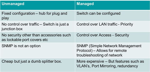
The major difference between them lies in the fact that managed switch can be configured and it can prioritize LAN traffic to make sure the most important information can get through. An unmanaged switch on the other hand behaves like a plug and play device. It cannot be configured and simply allows the devices to communicate with one another. Obviously the fixed configuration of unmanaged switches limits the functionality of a network to that of the Ethernet devices connected. That is the reasons why people would pay for more money to have a managed switch. Next part will go on to provide a clearer illustration to the benefits of using a managed switch.
Why to Use a Managed Switch?
Managed switch give you better control over LAN traffic and offer other advanced features to control the traffic.
- Redundancy
It refers to a back up data path to network traffic to safeguard a network in case a connection or cable fails. Managed switches incorporate Spanning Tree Protocol or STP to provide path redundancy in the network. This provides redundant paths but prevents loops that are created by multiple active paths between switches.
- Remote Management
Mission critical networks demand remote configuration, monitoring/traps, reboot, and re-imaging of OS. Managed switch use protocols such as SNMP or Simple Network Management Protocol for monitoring the devices on the network to realize remote management. The SNMP protocol allows you to relay network configuration data to network engineers and allow them to set configuration parameters remotely. This makes wire management and optimization functions to be performed from a central or remote location, which will make network management easier and more straightforward and can reduce troubleshooting time and increase uptime.
- Security and Resilience
Limiting network access to trusted devices prevents users from setting up unauthorized sub-networks. Managed switches enable complete control of data, bandwidth and traffic control over the Ethernet network, allowing you to set IP/port restrictions on actual physical ports. This means you can setup additional firewall rules directly in the switch. In all, managed switches support protocols which allow operators to restrict and control port access, like the 802.1x port based network access control. In addition, managed switches support protocols to limit management plane access via user authentication such as RADIUS, LDAP and others.
- Support Multiple VLAN Configuration
Managed switch can use the VLAN configuration to logically group devices as per the working departments and to isolate traffic between these groups. This segmentation and isolation of network traffic help to reduce unnecessary traffic. For instance, managed switches allow for the creation of multiple VLANs where 8-port switch functionally can become two 4-port switches (where ports 1-4 are VLAN 1 and ports 4-8 are VLAN 2). It’s possible to allow VLANs to talk to the router/NAT, while preventing them from talking to each other. You could lock down the wireless VLAN to only allow port 80/443 or similar so they can browse the web but nothing else.
- QoS (The Quality of Service)
The managed switches are able to prioritize one type of traffic over another allowing more bandwidth to be allocated through the network by assigning a higher priority to the critical traffic. This helps to improve network performance and helps in better transmission of delay-sensitive data such as real-time voice.
When and Where to Use Managed Switches?Managed switches possess all the above features, which are ideal for network applications with fast response time requirements at companies that need to allowing engineers to reach optimal reliable network performance and maintenance by managing and troubleshooting networks remotely and securely. These switches are robust and appropriate for Industrial Network settings, made to stand up to harsh applications like extreme temperatures (-40 up to +75), vibrations and shocks while contributing to a cost-effective, reliable, and secure network. Managed switches should be used on any network backbone switch so that segments of network traffic can be monitored and controlled such as: security/surveillance, defense/government applications, HVAC, water/waste water, utilities and oil/gas.
Conclusion
Managed switches are usually costlier than unmanaged switches, but it does offer many benefits for network control and configuration. This article has discussed a number of features found on managed switch, and introduce the major distinctions between unmanaged and managed switch. In the end, managed switches are supposed to be used on any network backbone switch so that segments of network traffic can be monitored and controlled, while unmanaged switches are the plug and play devices that are suitable for companies that has no advanced needs and limited budget.
Posted by: angelina at
02:32 AM
| No Comments
| Add Comment
Post contains 962 words, total size 7 kb.
August 31, 2016
Although cabling only represents less than 10 percent of the overall data center network investment, it outlives most network elements and treated as the most difficult and potentially costly component. With the datacenter cabling ranging from 1G to 10G, 10G to 40G and even to 100G, more complex cabling is required to ensure a good service or scalability for troubleshooting. In practice, there is no exact solution that will meet all of the cable management needs. However, two kinds of cabling systems can be applied—unstructured system and structured system. Just follow the guidelines and illustration highlighted in the article will go a long way to ensure you with the information required for the successful deployment of a cabling infrastructure in your data center.
Unstructured Cabling System
Unlike the structured cabling system with a managed patch panel, a unstructured cabling only occurs when optical links are deployed point to point or device to device without installing patch panels. In this situation, cabling pathways become congested with an entangled mess of two-fiber optical patch cords. Likewise, routing new patch cords in ceiling or floor trays all the way across a data center each time a new device is deployed is extremely inefficient.
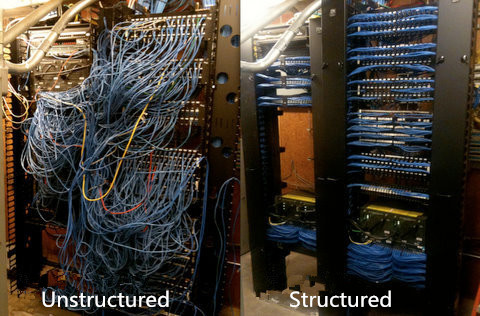
And this entanglement will bring difficulties in routing new patch cords in ceiling or floor trays all the way across the data center whenever a new device is deployed. That greatly influences work efficiency. What’s more, this system causes the overheating of data centers especially around the racks where cable clutter occurs.
Structured Cabling System
Structure cabling emerged as a way to better manage larger data center solution is a big step for the development of optical technology. Structured cabling system is a flexible, reliable and highly efficient for moving, adding and changing the infrastructure as the network grows. This kind of system requires additional investment on pre-terminated MPO cabling such as patch panel to create the cabling infrastructure.
Compared with the unstructured cabling, structured cabling architecture is generally easier to manage and more scalable. And, due to the use of trunked or shared horizontal cabling, it often carries a smaller cable footprint than direct-attach cabling. However, the flexibility of structured cabling presents potential downsides, including cost and link-loss budget. Nevertheless, existing large data centers will likely retain their structured cabling infrastructures, particularly for long-reach, zone-to-zone applications, where it generally remains the more practical choice. The following part will introduce 40G structured cabling solutions.
40G Structured Cabling Solutions
As noted before, structured cabling solutions allow for high consolidation of cabling into a compact patch panel, cabling and connectivity. The traditional duplex multimode SC or LC connections do not support 40G data rate standards, today the MPO technology is commonly found in cassette-based data center installation allowing for easy management and maintenance. Below are cabling solutions of 40G for cable management configurations with the use of MPO patch panel.
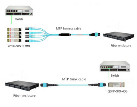
One method (seen in the above picture) uses MTP-LC harnesses to transition the MTP connector to LC leads through the use of fiber enclosure loaded with 4 fiber adapter panels (12xMTP Key-up/Key-down). This 12-fiber MTP to LC harness assembly breaks out 4 x LC uniboot legs connecting the SFP+ ports. The lengths of LC harness legs can be customized to adapt to different situations. But this often results in messy cable management. The other method uses MPO/MTP trunk cable and fiber enclosure loaded with 4 MTP high density cassettes (2 x MTP-12 to Duplex LC/UPC 10G OM4) to realize the interconnection. This 96-fiber 1RU rackmount fiber enclosure connects fiber patch cables LC to LC and MTP trunk cable. This method is specially used when the 4xLC ports are not located in close proximity on a single device or are being split between multiple devices. Because it’s more manageable to land the MTP trunk cables into fiber enclosure with individual LC ports for 4xLC patch cables.
Conclusion
Choose the most suitable cabling to support present and future network technology is essential for the long-standing performance of the data center. Structured cabling using an MTP cabling infrastructure is suitable for current 10 Gigabit Ethernet environments while maintaining protection for 40 Gbps environments and beyond. Compared with unstructured cabling, it might be a better solution for you. Except for the right knowledge of a structure cabling, the right tools, patience and discipline are also the key factors that will attribute to the masterpiece of your cable management in data center.
Posted by: angelina at
02:43 AM
| No Comments
| Add Comment
Post contains 744 words, total size 6 kb.
August 26, 2016
Generally for a home network, the most important consideration is the speed you have contracted for with your Internet service provider (ISP). And network adapters as an important element in wire management, are required to connect to the Internet with or without an Ethernet cable. There are many types of network adapters, an wireless one can help people connect to the home or office network as long as the computer is in the vicinity. This article will provide some information about network adapters that may be useful to potential buyers.
Main Features of Network Adapters
The wireless network adapter is quite similar to a memory stick in appearance. The device will usually insert into a USB port and has a LED light that indicates operability and power. The devices can be portable and quite effective. Some are slightly larger and may be the size of a credit card. Because of their size, the devices are convenient and easy to install. More designers are coming to appreciate the compactness of network adapters.
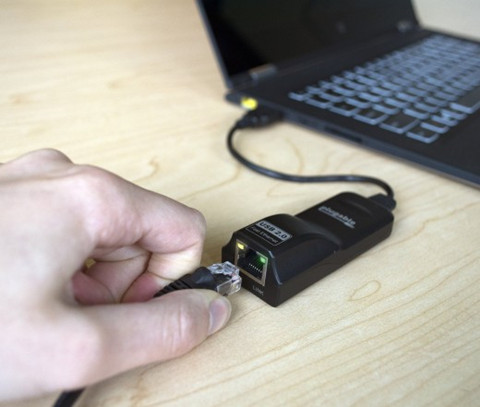
When the device is plugged in, it will scan for local networks to connect to and display them for the user. Users simply have to click the name of the network they wish to join. Any credentials that need to be provided should be provided, and this is all it requires to surf the network wirelessly. Most devices only require the credentials once, and it will boot each time it’s logged in.
The Important of Network Adapter
Network adapters are necessary for those who desire network connectivity. Network adapters bring so much more functionality and flexibility when it comes to connecting to the Internet. Wireless network adapters are even more desirable. Designers are recognizing that network adapters are instrumental to the success of the device. Local technology companies can provide network adapters at an affordable price to clients who need the functionality and the scalability. Network adapters are instrumental to connecting single or multiple devices to the Internet.
Software Drivers Are Necessary
Wireless network adapters need a piece of software called a device driver. These network drivers will allow applications to communicate with the network adapter hardware. When the network drivers are communicating with the hardware, the devices operate easier. Drivers can make current and past technology more compatible. If an upgrade is necessary from a PCI card or a PCMCIA, USB devices with update driver software is the preferable choice.
Backwards and Forwards Compatibility
Laptop computers will come equipped with a built-in WiFi card. When the wireless standards change and a new card is required, network adapters are usually backwards and forwards compatible. This is desirable if you want the newer and faster standard. For instance, most network adapters will support both the 802.11g standard and the 802.11n standard to ensure that they are both backwards and forwards compatible.
However to Ensure the Performance of Your Network Adapter
The network interface is where the data hits the computer. It’s the port or WiFi adapter that receives the data from the air or cable and translates it into something the computer can understand. No matter how fast the data arrives at the interface, it will only pass through as fast as the interface can process it. Many things can slow it down.
It’s important to remember that an interface that is capable of higher speeds than your network provides will not help things go faster. Spending money on a Gigabit network card won’t give you 1000 Mbps if your ISP is only supplying 25 Mbps.
Furthermore, a Ethernet cable in a cable management systems used to achieve the connectivity will also pose threat to the internet speed. Ethernet cables are presented in different categories. The most commonly used is Cat5, Cat5e and Cat6. CAT 5, rated at 100 Mbps; CAT 5e rated at 1000 Mbps; and CAT 6 rated at 10,000 Mpbs. CAT 5 is fine for most internet access through DSL or cable, while CAT 5e works well on connections over 100Mbps, as well as Gigabit business networks and home fiber optic connections. CAT 6 is probably overkill for most home networks, but is useful for business networks over 1 Gbps.
Other than cables used in home network, there are other factors that can throttle the performance of your network. Therefore, to use an external test server tests not only your home setup, including your adapter, but everything between you and the server doing the test.
Conclusion
To select the right adapter for your situation, you’ll want to have an adapter that exceeds the maximum speed of your network, while taking into consideration any likely future improvement.
Posted by: angelina at
02:36 AM
| No Comments
| Add Comment
Post contains 774 words, total size 6 kb.
August 24, 2016
As audio video systems and installations have become more complex over time, it is common for people to use HD TVs, HD media players, and other home theater systems. Additionally there seemed to be a big variance in quality between brands, especially when it came to extending HDMI signals. Therefore, the introduction of HDMI technology is a game changer and highly appreciated by overall users in this days. Just as fiber jumper connecting optical equipment, HDMI cables offer long-distance HD audio and video signals transmission playing an important role in achieving brilliant performance. Today’s article will have a brief introduction to this cable.
HDMI Cable
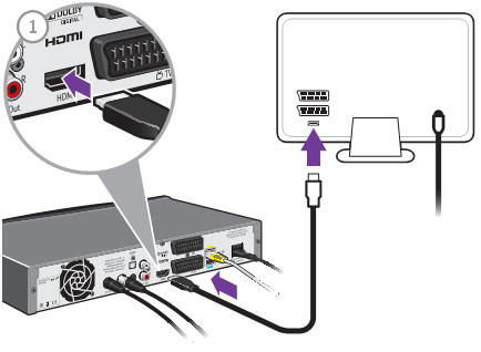
HDMI ((High-Definition Multimedia Interface) cable is composed of four shielded twisted pairs with several separate conductors for transferring data over video/audio devices. A HDMI cables are defined into two cable categories: one is the Category 1-certified cables, known as standard HDMI cables, the other is Category 2-certified cables, also called high speed HDMI cables. HDMI cables has not been specified the transmission length. A cable of about 5 meters (16 feet) can be manufactured to Category 1 specifications easily and inexpensively by using 28 AWG conductors. With better quality construction and materials, including 24 AWG conductors, an HDMI cable can reach lengths of up to 15 meters (49 feet). HDMI cables are expensive than the regular Cat6/Cat7 cables. Just as anything else, whether you want to use the expensive but high-performance HDMI cables or cheap but low-performance Category copper cables like Cat5e/Cat6, it depends on what inputs you tech has. The below part lists the current usage of HDMI cables, and you can look at the solutions that interest you. The following image shows the image of a HDMI cables connecting box and HDMI socket of TV.
Difference Between an HDMI Cable and a DVI Cable
HDMI cable and DVI cable as two two input-output media interfaces in home network are posing difficulty in distinguishing them. In fact, the biggest difference between these two transmission media lies in their layout. An HDMI cable is more compact and resembles a USB cable, while a DVI cable is usually bigger in size. Another major difference is in capability: the HDMI supports audio and video, whereas the DVI is strictly video-only.
Applications of HDMI Cables
- Boosted HDMI: HDMI cables, with a booster integrated into their structure use the 5v power rail of the HDMI signal to carry the data further without loss of fidelity. This cable, compared with the normal HDMI cable, is intended to make longer cable runs, but it can also be used to make a short cable thinner and much more flexible. HDMI cables with integrated booster chipsets are more expensive than their basic counterparts, and so far only cater to 1080p content due to the loss of bandwidth over the extended length, but they can reach 40 meters.
- HDMI over CAT: It is not a new concept to use Cat5 or Cat6 cables to extend an AV source. HDMI recently make use of this technology for stable extended runs—sometimes even using existing network cabling. Due to bandwidth limitations, most CAT extenders only support 1080p, but some can handle 3D, too. Configuration is more complex than regular cables, and interference can be a big problem in some environments, but with a good HDMI over Cat5/6 Extender, you can run 50 meters.
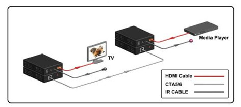
- HDMI over Fiber Optics: Fiber optics for HDMI, compared with HDMI over CAT, carries the highest price premium, but they have the much better capacity to outstrip copper based cables for distance by a large margin. The added benefit to this cable type is flexibility with a maximum distance of 45 meters. The optical core is much smaller than Boosted HDMI, but can go the same distances. Note that some companies have kits which run much longer, but it of course will cost far more!
- HDMI over Wireless: Wireless technologies vary between models, but one thing they have in common is they don't generally go as far as cables do. Line of sight is 10 to 15 meters, and through walls can be as low as 5 to 8 meters. Unless you can't run a cable at all, a lead will beat Wireless every time. Wireless is also limited by bandwidth to 1080p, and only the best units can handle 3D.
Some Terms Appeared in the Above Part
1080p refers to an HDTV format which has 1080 horizontal lines of resolution. The p stands for progressive scan. The traditional analog video uses an interlaced scan, which draws the odd lines, then even lines of each frame in sequence.
AWG is short for American Wire Gauge, which is a common unit of wire measurement. AWG expressed in a HDMI cable refers to the size of the conductors within the cable. With wire gauges, smaller numbers actually refer to larger wires. This means a 24 AWG cable has a thicker conductor than a 28 AWG cable. The benefit of a thicker conductor is the ability to effectively transmit an HD signal.
Plenum refers to the air-handling spaces in building construction above the ceiling and beneath the floors. Some building codes require Plenum-rated cable, which has a low-smoke jacket that burns slower in the event of a fire and emits less toxic smoke.
Summary
This article isn’t a definitive guide to HDMI cables, but for the sake of simplicity we just provide some basic information about industrial and commercial applications of HDMI cables. If you are on the fence to install a fiber optic network, always use the shortest length of cable you can live with, and ensure they're certified by the industry bodies. What’s more, it is advisable for you to save your money for other home network components and get your HDMI cables as cheaply as possible.
Posted by: angelina at
03:24 AM
| No Comments
| Add Comment
Post contains 968 words, total size 7 kb.
August 17, 2016
When planning for a long-term cabling solution for your data center, it is important to consider future transmission speeds and the infrastructure to support them. Data center houses equipment like servers, storage units, backup power supplies and other equipment, which act as the heart of a building or campus. And all these equipment require high-bandwidth cables to connect them. The cabling in data center mainly comes in two forms—fiber or copper. To link the devices in data center, unshielded twisted pair (Cat5e/Cat6) and fiber optic fibers (MM fiber patch cords and single-mode fiber) are commonly used. This article will focus on cabling solution for data center, and provide the cost-effective solution to you.
Twisted Copper Solutions For The Data Center
2006 witnessed the publication of the the IEEE 802.3an standard, meaning that users can use the twisted copper cabling or 10GBASE-T to support 10 Gigabit Ethernet. Compared with the former IEEE 802.3ak or 10GBASE-CX4 standard, 10GBASE-T standard has the advantage of supporting 10 Gigabit Ethernet up to 100 meters. What’s more, the 10GBASE-T using structured wiring systems based on the RJ45 connector is less costly than the 10G optical transceivers for supporting the same Gigabit Ethernet. All this attributes to the development of the copper twisted-pair cabling for horizontal, or non-backbone, distribution between LAN switches and servers.
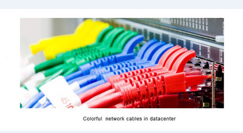
UTP (unshielded twisted pair) cabling is a widely adopted copper cabling solution due to its support for both voice and data applications. A UTP cable consists of insulated, copper wires twisted around each other to reduce crosstalk and electromagnetic induction between pairs. Typically a twisted pair will be enclosed in a shield (STP) that works as a ground; in other cases (UTP), the pair remains unshielded. UTP cables are often referred to as a Category cable, such as Cat5e, Cat6, or Cat7, etc.
Cat5e cables had been the standard solution and often used for legacy equipment or lower bandwidth needs. But Cat6 is the most common copper type in new installations today, especially for 10G Ethernet application. Cat5e will soon be going away, with available options being Cat6, Cat6a and Cat7. These options offer increased levels of performance and improved installations. All of these cable types can adequately provide you a connection. The differences between them lie in their transmission speed capabilities and costs.
Fiber Optic Solutions For The Data Center
In a data center, bandwidth distributed to servers and other devices may range from 1 Gbqs to 10 Gbqs or more depending on application and data center models. Fiber optic cabling are usually worshiped by overall users owing to numerous advantages. For instance, compared with copper cabling, fiber systems can provide up to 60 percent space savings over copper cabling, and it also have a greater bandwidth and error-free transmission over longer distances allowing network designers to take advantage of new data center architectures.
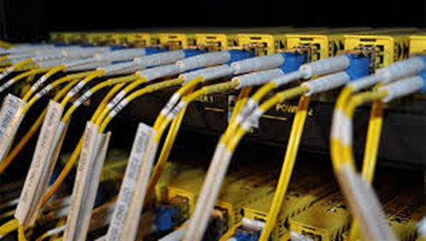
In practical terms, fiber cables are comprised of light, which reduces signal interruption, allowing for signals to be carried longer distances seamlessly. Though fiber cables are highly sought after, the cost to purchase and install has decreased throughout the years, making them a reasonable choice for companies seeking a reliable, scalable solution. The fiber optic cables can be mainly divided into two parts, that’s multimode and single-mode fibers.
The multimode fiber type can be separated into categories: OM1, OM2, OM3, OM4. Applied for short distances, multimode fibers have a high light-gathering capacity, meaning the use of lower cost, lower wavelength technologies like LED and vertical-cavity surface-emitting lasers (VCSELs) can be employed. For longer distances, single-mode OS1 and OS2 are used; single-mode fiber uses lasers to achieve higher speeds and further distances. Additionally, fiber optic cable terminated with different optical connectors (like SC fiber cable) are also widely utilized in data centers. Fiber optic cables are critical to network performance as they do more than join servers and connect switches. They are the foundation of your technology environment. Thus it is important to have the best options for your optical network.
Field-terminated vs. Pre-terminated Fiber Solutions
In commercial building installations, an optical fiber cabling link is typically assembled in the field at the job site. The cable is pulled in from a reel of bulk cable, cut to length, attached to the patch panel housing and terminated with field installable connectors on each end. The terminated ends are then loaded into adapters in rack or wall mountable housings. Finally, the complete link is tested for continuity and attenuation.
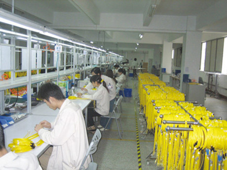
The most efficient optical infrastructure is one in which all components are pr-eterminated in the factory see in the above picture. Connectors are installed, tested and packaged in the factory. The installer unpacks the components, pulls the preconnectorized cable assembly into place, snaps in the connectors and installs the patch cords connecting to the end equipment. This is the fastest installation method and provides the best solution for turning up servers quickly and lessening the risk of not meeting the customer’s availability expectations. The design and product selection process remains the same with selection and specification of fiber type, fiber count, cable type, connector type and hardware type appropriate for the environment.
Conclusion
There is no absolute solution to utilizing fiber or copper cabling for data centers. Twisted pair cabling wins the broad acceptance among users owing to the horizontal medium, low initial cost, and the ability to deliver higher data rate LAN services and the flexibility to use one medium for all services. Therefore, in the majority of situations, copper cabling remains the preferred choice for the final link to the desktop, and other short links such as those found in data centers. However, with the speeds increasing and more copper cables installed, copper-based LANs will require more complex and expensive electronics. It might be inappropriate or impractical to implement in many current building environments.
While fiber optic cabling’s significant bandwidth distance gives it advantages over twisted pair in centralized architectures. Thanks to its high performance and high density, fiber optic cabling becomes an important factor where equipment density and heat dissipation are a concern. To sum up, whether to use copper or fiber for network cable type, the data center must have the best and fastest cabling.
Posted by: angelina at
03:55 AM
| No Comments
| Add Comment
Post contains 1039 words, total size 8 kb.
August 16, 2016
If you are still using a 100BASE network, or GBIC transceiver for a small office, you may run into the limitations of last decade's technology. Because the 100BASE standard network is just fine for a small office, but it isn't sufficient to handle heavier network use. As your network expands, you might experience problems like: dropouts in your VoIP calls, Sluggish data retrieval speeds, or poor video streaming quality. If you have encountered any of this, maybe it’s time to start thinking about an upgrade to gigabit Ethernet, which moves at ten times the speed of traditional Ethernet. This article will explain the Gigabit Ethernet in the following aspects: the compatible SFP transceiver, the difference between twisted copper and fiber optic Ethernet.
Compatible SFP Transceiver
When contemplating an upgrade to gigabit Ethernet, there are a number of issues involved in the network transition. But one of the most immediate concerns people have is how much new hardware they'll have to purchase. The good news is that one of the basic issues providing connectivity is generally quite easy.
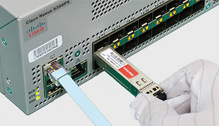
The representative of the optical transceivers for Gigabit Ethernet is Small Form-factor Pluggable (SFP). These Small Form-factor Pluggable slots allow transceivers like the GLC-SX-MM to be plugged in and provide instant gigabit Ethernet connectivity. In the last few years, when you purchased your networking equipment, it should have some industry-standard SFP ports, based on a Cisco standard. And you can only purchase the original expensive SFPs. However, the monopolized SFP market is unhealthy for the development of optical technology, nowadays people can appreciate the low price and high performance of compatible SFP transceivers from OEM vendors.
How to Ensure the Compatibility of the SFP Transceiver
Although the OEM or alternative party compatible SFP transceivers are much cheaper than the original ones, people are hesitated to use them. In fact, there are mainly two factors that will have an impact on the compatibility of the SFP transceivers. First, does the SFP optics require DDM function? Second, does the host equipment check the ID code and lock out alternative party components?
Certainly from our experience, most Cisco core equipment and routers do lock out all but Cisco ID SFP modules. We do not have an extensive report on what Cisco equipment does and does not lock out third party SFP.
The only way to know for sure is to try an authorized component if the host equipment rejects it. Remember, the compatibility has nothing to do with the functions of the transceiver, only in recognizing ID code and selecting to lock out third party SFP or not.
Fiber Optic Cabling Over Copper-wire Cabling
Choose to use copper-wire cabling or upgrade to fiber optic cabling in your offices is another consideration when installing a network. There is no doubt that fiber optics provide several advantages over copper, but it is more expensive than copper cabling. In addition, fiber optic supports far longer cable lengths than twisted copper.
Copper can only run for around 100 meters, whereas fiber can go between 200 and 500 feet, or more, without signal loss. Fiber has gives off no radio interference, allowing it to coexist more easily in an office with a lot of wireless devices. Because of the lack of interference, fiber is also harder to hack into than copper.
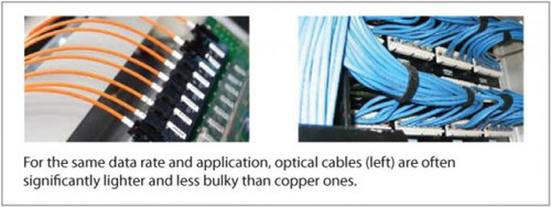
For equivalent data rates, optical cable is thinner and lighter than copper wire, and it does not need to be shielded. For these reasons, an optical cable is often lighter in weight and less bulky, and has a smaller bend radius, than the equivalent copper cable, especially with longer cables. These advantages of fiber provide more data center configuration flexibility.
Just as with copper, a standard GLC-SX-MM transceiver links fiber optic Ethernet with your existing equipment. Or the GLC-SX-MM-RGD transceiver is also just great for your network, which is the 1000BASE-SX SFP GLC-SX-MM transceiver with DOM support.
For future proofing, moving away from copper is probably a good idea. Fiber optics are growing steadily in popularity among businesses which have taken over large office buildings, created expansive complexes, or need to collaborate with remote offices in real time.
Additional Information
The biggest advantage of Cisco's SFP system is that it's entirely hot-swappable. It doesn't matter what the device is, from servers to your switch to simple Ethernet cards: If it has an SFP port on it, it can support a multitude of transceivers for different functions, through one standardized interface. In fact, that standardization means that third parties can produce transceivers which are as good as official Cisco units. So, if you decide that fiber optic gigabit Ethernet is what you need for your future business communications needs, the GLC-SX-MM transceiver is truly simple to install and use.
Conclusion
End-users are wondering about whether they should upgrade to higher-bandwidth network as the existing network like 100BASE standard is fine for their network. However, the transition to higher internet speed is going to happen sooner or later. There are several different gigabit Ethernet standards out there, so keep in mind to see which best fits your vision for the future of your business. Note that you'll need transceivers like the GLC-SX-MM to connect your existing devices to the new network.
Posted by: angelina at
03:24 AM
| No Comments
| Add Comment
Post contains 878 words, total size 7 kb.
August 11, 2016
Cisco system introduced the Nexus series switch in 2008 that are modular and fixed port network switched designed for the data center. The Cisco Nexus series switches ranges from Nexus 1000v, to the newly released Nexus 9516, which are warmly welcomed by users. This article will introduce the Cisco 6004 switch and highlight its 10G and 40G cabling options.
Cisco Nexus 6004 Switch
Cisco Nexus 6004 switch is a model of Nexus 6000 series. Previously,, the Nexus 6000 series was meant to be focused on the Cisco 40G aggregation products, and the 5500 and 5600 series on 10G. However, Cisco decided to merge the product portfolios. Thus Nexus 6000 series switch delivers high-density 10 and 40 Gigabit Ethernet connectivity in an energy-efficient, compact form factor, so does the Nexus 6004 switch.
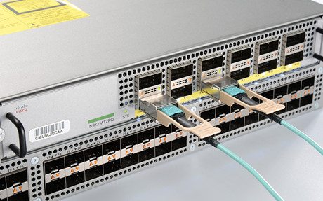
The Cisco Nexus 6004 switch is a high-density, low-latency, high-performance device for 10G & 40G Ethernet and Fibre Channel over Ethernet (FCoE) infrastructure, with a compact four-rack-unit (4RU) switch providing line-rate Layer 2 and 3 switching. This switch offers 48 x 40-Gbps ports on the base of the chassis and 4 line-card expansion module (LEM) slots; 12 x 40-Gbps port LEMs can be plugged into each slot, for a system total of 96 x 40-Gbps ports in an Enhanced Quad Small Form-Factor Pluggable (QSFP+) form factor.
Features and Capabilities of Cisco Nexus 6004 Switch
- High-performance—The Cisco Nexus 6004 can support up to 384 SFP+ connectivity over breakout cables or 96 40 Gbqs line rate. It also offers unified ports for LAN and SAN convergence.
- Future Proof—The Cisco Nexus 6004 support for all the card expansion modules across the 6004 Chassis. The Cisco Nexus 6004 is also equipped with eight expansion slots for accommodate network growth.
- Operational Efficiency—This switch is equipped with advanced analytics toolkit, VXLAN support for virtualized and cloud deployments (supported on Cisco Nexus 6004X), and dynamic Fabric Automation (DFA) and PowerOn Auto Provisioning (PoAP) for automated virtualized and cloud deployments.
Cabling Options for Cisco Nexus 6004 Switch
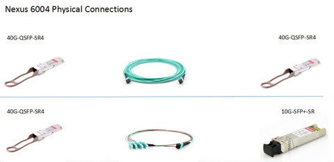
As noted before, the Cisco Nexus 6004 switch offers 10G and 40G connectivity. Numerous 10 and 40 Gigabit Ethernet connectivity options using Cisco 40GBASE QSFP and QSFP+ breakout cable can be used in this switch. The following image presents two physical connections for Nexus 6004 switch.
In a 10G deployment, a permanent structured cabling link would be deployed using these MTP-based trunks to create connector patching fields at each end. Then short MTP or LC jumper patch cables would be used to make the connection from the patch field to the QSFP+ or SFP+ optics at the switch port. The MTP patch-panel field allows the end device to be connected to any port across multiple Cisco Nexus 6004 devices because the devices terminate at the patch-panel field. The following figure shows a Cisco Nexus 6004 that is connected to the base ports of a Cisco Nexus 5500 platform switch.
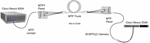
These endpoint connections will be MTP and LC, respectively, and the structured cabling infrastructure maintains MTP trunks and panels. This approach will require a MTP-to-LC harness assembly to make the connection from the termination patch field to the Cisco Nexus 5500 platform. A MPO jumper can be used to make the connection from the termination patch field to the Cisco Nexus 6004.
For 40G connectivity, Cisco Nexus 6004 switches can support 40G direct attach cable (DAC) integrating QSFP connectors for short-reach 40G application, or supporting 40G active optical cable (AOC) for longer-reach application. FS.COM provides a full range of 40G QSFP+ DAC cables including passive (lengths up to 7m) and active cables (lengths up to 10m). In addition to the QSFP+ to QSFP+ DACs, it also offers the QSFP+ to 4 x SFP+ breakout DACs which are ideal for Cisco device user to run 40G over existing traditional 10G backbones.
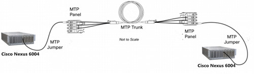
The image below shows the 40G cabling connectivity between two Cisco Nexus 6004 switches. The MTP trunk cables used in this configuration create permanent fiber link between patch panels, and allow full support of 40Gbqs flows between the devices.
Conclusion
The Cisco Nexus 6004 switch provides can be deployed in multiple scenarios—direct-attach 10G and 40G Ethernet access and high-density fabric extender aggregation deployments. For those who want to upgrade to 10G Ethernet, the switch scales up to 384 ports of 10G Ethernet interfaces. And you can easily meet increasing demand for 40G Ethernet connectivity up to 96 QSFP+ interface ports. What’s more, the Cisco Nexus 6000 series can adapt to increasing bandwidth demands with low power and a compact space profile, providing savings in capital expenditures and operating expenses.
Posted by: angelina at
03:12 AM
| No Comments
| Add Comment
Post contains 765 words, total size 7 kb.
August 10, 2016
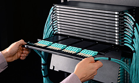
The data center is the heart of a fiber optic network. To ensure its long-term reliable network performance, all the optical equipment within data center should be well organized. However, the current multi-fiber counts and high-density optical cabling put strain in the cable management. Fiber patch enclosure provides solid fiber-optic-link protection and space-saving cable management, which is becoming a must-have component in data center. There are several fiber optic enclosures available on the market that are widely utilized in data center or server room. This article will briefly introduce the commonly used fiber enclosure designs to better meet your data center requirement. LC to LC fiber cable and patch panels are mounted in a fiber enclosure in the following picture.
Fiber Enclosure Designs
Rack mount fiber enclosure is the commonly used type in data center as it provide a convenient and rugged termination point for fiber jumper cables. This rack mount enclosures offer a flexible connectivity system using a variety of adapter plates and MPO cassettes. The enclosures work equally as well with armored cable as they do with multiple trunk cables and are available in 1U-4U versions.
1U enclosures fit standard 19-inch racks and have rear cable management rings. 2U, 3U and 4U enclosures are designed for side or rear trunk cable entry, have removable front and rear covers, edge guards on the front for cable assembly protection and front and rear cable management rings. 2U, 3U and 4U enclosures also fit standard 19 and 23-inch racks and have a clear plastic, removable front door that can be outfitted with a label for easy identification of connections.
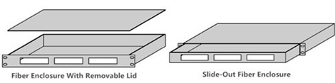
Except for different size, there are two types of rack mount enclosures: fiber enclosure with a removable lid and slide-out fiber enclosure (see in the following figure). The slide-out version is typically more expensive than the other version. But slide-out fiber enclosure can allow customers to remove the whole enclosure from the rack, thus, it can provide easier internal fiber connection access.
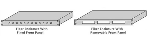
As for the design of the fiber enclosure front panel, two commonly used types are fixed front panels and removable front panel. The fixed front panel can be loaded with appropriate fiber optic adapters, while the removable front pane can accommodate several fiber optic adapter panels or cassettes just as seen in the following image.
How to Select the Fiber Enclosure
If this is your first time to install a fiber optic network, you should follow the instructions below. Only in this way can you satisfy your installation requirement, and matched your budget as well.
- Physical requirement
First, list all the requirement that will be mounted in the enclosure and their complete measurements:height, depth, width, weight. All of these figures will ultimately determine what type of fiber enclosure you will need. Note that always select a bigger fiber enclosure for all your existing equipment as well as for future proof.
- Critical accessories
A fiber enclosure should provide plenty of grommeted access points through the rear and top of the cabinet, as well as through the bottom for raised floor installations. Not only are the fiber optic cables mounted in the fiber enclosure, but devices like hubs, routers, patch panels, and monitors are needed to be mounted in the enclosure-network.
All servers should be protected by an uninterruptible power supply(UPS) system, available in a variety of rack-mount configurations. Thus power protection is needed. Remember that any accessories that are not rack-mountable will require additional trays, shelves and mounting accessories.
- Budget
Money is always a main considerations. Thus choose the fiber enclosure that can meet your premium features at a very competitive price is the number one task. People are usually in a dilemma about whether to choose a equipment that are suitable for now or the expensive one for future proof. It is hard to say, but a premium enclosure is a durable item that will provide services for years to come.
Summary
High density fiber enclosures can maximize the amount of active equipment in a data center by minimizing the footprint of the networking infrastructure, but there’s a problem—all that fiber in a small amount of space creates problems when changes need to be made. Therefore for easiest access, quick-release side panels should be a top priority when selecting an enclosure.
Posted by: angelina at
04:01 AM
| No Comments
| Add Comment
Post contains 720 words, total size 6 kb.
August 03, 2016
In the fiber optic network, a carefully constructed network requires calculated planning and a high level of installation. It is not as easy a cavemen can do it, as many factors should be taken into account when installing a fiber optic network, such as construction costs, time constraints, existing infrastructure, and so on. There are two main types of land based network fiber optic installation—aerial and underground. This article will talk about these two cable installations in detail.
Aerial Fiber Construction
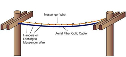
The fiber optic installation that occurs when fiber jumper is installed along a line of utility poles, is known as aerial fiber construction. When installing a placing aerial cable, besides the cables, a support strand is needed as well. A support strands can be deployed along the route first, with fiber pulled and lashed to the support strand later. Or the aerial fibers can be pre-lashed, making the installation less complex. Lashing refers to the process of securing the fiber cable to the support strand via lashing wire. When placing cable on a pole, the required spacing distance varies depending on the type of cable or equipment. These requirements are often set by local, state and national standards.
Underground Fiber Construction
Underground fiber construction refers to the fiber installation that occurs when fiber optic cable is installed under the ground in pipes, or conduits. The depth of the underground cables varies by many factors; however, it is typically between 12-36 inches below surface level. In underground fiber construction, the fiber optic cables are buried in a trench, but In colder areas, fiber cables are buried below the frost line to protect the cables from being damaged.
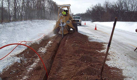
There are three main subcategories of underground fiber installation including direct buried, air-blown or micro trenching. In a direct buried cable construction, the fiber optic cable is installed directly into the ground rather than in protective conduits. When fiber optic cable is installed through a conduit via air, the process is known as air-blown or cable-jetting construction. And in air-blown installation, a device injects a high volume of air into the duct at high pressures to blow the cable through. Micro trenching construction occurs when the fiber optic cable is installed underground by way of a small groove, instead of a larger trench. Each of the above underground installations have a variety of benefits and are used in varying, and case specific scenarios.
Pros and Cons of Aerial and Underground Deployment
Aerial cables are one of the most preferred and cost-effective solutions for the end user, because installers can reuse existing pole infrastructure without digging up another roads to bury cables or ducts, what’s more, aerial cable construction is easily modified to add additional capacity.
However, aerial deployment is more susceptible to damage. The falling tree branches, high winds or ice storms, vehicle accidents, animals that chew on the fiber all can make the aerial cable strain or break. Therefore, calculations on the strength of both the cable and poles need to be taken into account when determining span lengths.
But it will typically takes some time and money to make ready requirements if poles and cable need to be made stronger. It is a good solution to the areas with existing pole networks or rural environments without urban restrictions.
While many customers do prefer their services, including fiber cables, to be installed underground. Unlike the aerial deployment, buried fiber deployments are less susceptible to wind and ice damage as they are buried below the layer, which makes it often at least ten times more reliable than aerial routes, especially where poor weather is common.
However this might be a costly solution because the cable needs to be buried deep in the ground to protect it from accidental damage. The deeper an operator has to dig, the more costly it is. Never to mention that if a buried direct cable is broken, it is expensive to repair. These buried direct cables cannot be removed and replaced because it tends to be firmly anchored into the ground.
Conclusion
As this blog shows, choose which method to install a fiber optic network will depend on a variety of factors including the landscape, cost of the labor and equipment, and so on. Both of the two deployment methods presents advantages and disadvantages that must be carefully evaluated by case basis.
Posted by: angelina at
03:51 AM
| No Comments
| Add Comment
Post contains 732 words, total size 6 kb.
July 29, 2016
Ethernet cables are the standard cables used for almost all purposes that are often called patch cables or fiber jumper. In an article "How to Choose Ethernet Cableâ€, we know that Ethernet cables can be categorized into many types, like straight-through and crossover Ethernet cable, UTP or STP, Cat5 or Cat6, etc. But we know little about the pins and wiring in Ethernet cables and RJ45 plugs.
RJ-45 conductor cable contains 4 pairs of wires, each consisting of a solid colored wire and a strip of the same color. There are typically two wiring standards for RJ-45 wiring: T-568A and T-568B. What do they mean, and why they are important? This post will discuss the color diagram of straight-through and crossover Ethernet cable to help you figure out.
Straight-Through and Crossover Cables
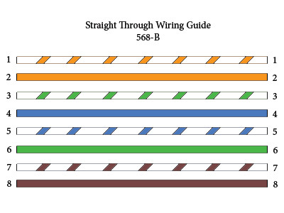
Straight-through refers to the Ethernet cables that have the pin assignments on each end of the cable—Pin 1 connector A goes to Pin 1 on connector B, Pin 2 to Pin 2 etc. Straight-through wired cables see in Figure 1 are most commonly used to connect a host to client. For example, the straight-through wired cat5e patch cable is used to connect computers, printers and other network client devices to the router switch or hub (the host device in this instance).
While an crossover cables are similar with straight-through cables, except that TX and RX lines are at opposite positions on either end of the cable, in other words, Pin 1 on connector A goes to Pin 3 on connector B. Pin 2 on connector A goes to Pin 6 on connector B ect. Crossover cables are most commonly used to connect two hosts directly.
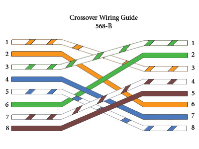
What’s more, the color code diagram of these two cables are different. To create a straight-through cable, you will use either T-568B or T-568A on both ends, while to create a cross-over cable, you will wire T-568A on one end, and T-568B on the other end.
T-568B and T-568A Standard
T-568A and T-568B are the two wiring standards for RJ-45 connector data cable specified by TIA/EIA-568A wiring standards document. T-568A standard ratified in 1995, was recently replaced by the T-568B standard in 2002. The difference between the two is the position of the orange and green wire pairs. It is preferable to wire to T-568B standards if there is no pre-existing pattern used within a building.
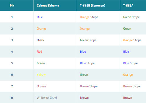
Both the T-568A and T-568B standard Straight-through cables are used most often as patch cords for your Ethernet connections. If you require a cable to connect two Ethernet devices directly together without a hub or when you connect two hubs together, you will need to use a Crossover cable instead.
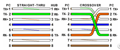
Looking at a T-568A UTP Ethernet straight-through cable and an Ethernet crossover cable in the above image with a T-568B end, we see that the TX pins are connected to the corresponding RX pins, plus to plus and minus to minus. You can also see that both the blue and brown wire pairs on pins 4, 5, 7, and 8 are not used in either standard. What you may not realize is that, these same pins 4, 5, 7, and 8 are not used or required in 100BASE-TX as well. So why bother using these wires, well for one thing its simply easier to make a connection with all the wires grouped together. Otherwise you’ll be spending time trying to fit those tiny little wires into each of the corresponding holes in the RJ-45 connector.
Conclusion
Ethernet cable color-coded wiring standard allows optical technicians to reliably predict how Ethernet cable is terminated on both ends so they can follow other technicians' work without having to guess or spend time deciphering the function and connections of each wire pair. There is no technical difference between the T568A and T568B wire standard, so neither is superior than the others.
Posted by: angelina at
07:18 AM
| No Comments
| Add Comment
Post contains 650 words, total size 5 kb.
July 27, 2016
The Cisco GLC-LH-SM optical transceiver, as one type of SFP transceivers, presents a huge change in the ease of incorporating fiber optic technology into enterprise networking. SFP transceivers does not need to be configured to begin function, and offers internal calibration to optimize data throughput. And, being hot swappable, it can be assured that other network components would keep online during the replacement of the SFP transceivers. Cisco GLC-LH-SM is 1000BASE-LX/LH SFP, which is widely used in optical network systems. High-quality Cisco Compatible GLC-LH-SM is offered only $7 at Fiberstore. Here is what you need to know about Cisco GLC-LH-SM.
Features of GLC-LH-SM
Cisco GLC-LH-SM is the 1000BASE-LX/LH SFP compatible with the IEEE 802.3z 1000BASE-LX standard. Unlike other Cisco SFP transceivers that can operate either on single mode or multimode fibers, GLC-LH-SM can support on standard single mode fiber-optic with a link span of up to 10 km and up to 550 m on any multimode fibers. This industry-standard Cisco Small Form-Factor Pluggable (SFP) is a hot-swappable input/output device that plugs into a Gigabit Ethernet port or slot, linking the port with the network.
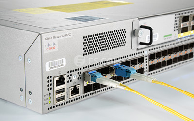
The GLC-LH-SM, can be used and interchanged on a wide variety of Cisco products and can be mixed in combinations of 1000BASE-SX, 1000BASE-LX/LH, or 1000BASE-ZX on a port-to-port basis Cisco Catalyst 6500 or 7600 Series Supervisor Engine 720.
Advantages of Cisco GLC-LH-SM Optics
Generally speaking, widespread adoption of fiber optic networking has been extremely high precision demands and delicate construction that came along with the media; but fiber optic cables made of glass-like material can easily damage. Also, the interfaces on either end of the cable have often been required to be very expensive, highly complex transceivers that required a large amount of intricate configuration to perform optimally, which becomes the main obstacle of the widespread adoption of fiber optic networking.
However, with Cisco GLC-LH-SM fiber optic transceivers, the challenges are a thing of the past. Here are three ways that the GLC-LH-SM transceivers make fiber optic networking very possible.
1. There is no need for Cisco SFP transceivers to configuring before function, and it also offers internal calibration to optimize data throughput.
2. Another unique advantage of fiber optics is that these SFP transceivers are truly hot swappable, which means a transceiver failure can be solved by simply replacing a new one, then you network is back online and ready to go.
3. GLC-LH-SM fiber optics also has a single or multimode operations. Single mode allows data transmission over distances exceeding 10km, useful for very large research facilities, hospitals, or university campuses. And multimode fibers open the data floodgates, giving you maximum throughput upwards of 1.25 Gbps so that this transceiver can meet your needs whether a network solution that covers a long distance, or the huge bandwidth fiber optic.
FS.COM Compatible Cisco GLC-LH-SM Optics
For the past decade, we have led the industry in manufacturing and delivering world-class products that improve the way we communicate. Cisco compatible GLC-LH-SM is offered at the minimum price of $7 in FS.COM, which is much lower than that in Amazon ($34).
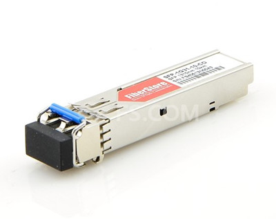
FS.COM 1000BASE-LX/LH SFP can be used in Gigabit Ethernet, Fibre Channel, switch to switch interface, switched backplane applications, router or server interface and other optical transmission systems. Besides the compatible 1000Base-LX/LH SFP modules, we also provide the 1000BASE-EX (like Cisco GLC-EX-SMD), 1000BASE-SX (like Cisco GLC-ZX-SM), 1000BASE-BX (like Cisco GLC-BX-D) and so on.
Conclusion
Fiber optic technology has been around for several decades now, and is sure to be the future transmission media for network backbone and other high-demand applications. Cisco GLC-LH-SM, as an old established Cisco SFP transceivers, wins large market share in telecom field. Cisco GLC-LH-SMD is a new type of GLC-LH-SM with a added function of DOM, which you can also buy it from the market.
Posted by: angelina at
03:02 AM
| No Comments
| Add Comment
Post contains 635 words, total size 5 kb.
July 20, 2016
Fiber optical technology typically presumes a service life of nearly 30 years. It is not a revolutionary or a new technology, in fact it is only about carrying light from one point to another. The questions that frequently asked around the industry are the art of mysticism, thus this post has collected questions made by professional during seminars, forum and projects. Solutions are also provided respectively to help readers to form the general understanding of this system.

Do signals really travel faster in fiber optics?
The speed here doesn’t refer to the the speed of signals in fiber optic cable, but the bandwidth potential of the fiber. Because you know that the speed of light in glass is about 2/3 C, but you might be surprised to know that signals in UTP (unshielded twisted pair) cables like Cat 5e travel at about the same speed (2/3 C). Coax, meanwhile, has a faster NVP (nominal velocity of propogation), about 0.9C, due to it's design.
What do I need for connecting Optic Fiber Cable to a Cat 5 Cable?
You need a media converter available from a number of companies for nearly $100-200.
Do you see any real serious problems in splicing together fiber cables from different manufacturers, as long as the cable is manufactured to the same specifications?
No, not as long as they are the same type and size, for example, multimode 62.5/125 or 50/125 and single mode should be normal (non-dispersion shifted) or dispersion shifted. Some single mode fibers are made for 1300 nm only, 1550 nm only or both, and they should not be mixed. Note that there are some other single mode fibers that have special coatings that cannot be mixed with others. Therefore you are supposed to ask your fiber vendors, splicer supplier or try it first before going into the field!
Will a single mode connector work on multi-mode cable?
The answer is maybe you can use SM connectors on MM but not the reverse. SM connectors are made to tighter tolerances—as is SM fiber—so the ferrule hole may be too small for some MM fibers. MM connectors have bigger holes for the fiber and will have high loss (>1dB) with SM. Also MM connectors may not be PC (physical contact) polish - terrible for return loss. MM fiber may not fit the smaller hole in SM connectors.
If you have a 50 micron fiber backbone, can you use 62.5 fiber jumpers on each end?
NO! On the receiver end it is OK, but on the transmitter end, the larger core of 62.5 into smaller 50 micron fiber will have fiber losses of 2-4 dB.
What is your view on using fiber optic connectors? Is it a better terminating method than fusion splice?
Of all the SFF (small form factor connectors), LC connector is the one that has become the most popular. In fact, it is the de facto standard connector for gigabit and 10 gigabit networks. Indeed the design is very well thought out. The smaller ferrule of a LC to LC fiber cable is easy to polish well and has excellent mating performance—which leads to low loss and back reflection. It is also easy to terminante and test.
What is the theoretical lifetime of optical fiber and optical fiber cables?
There is no "theoretical lifetime†of optical fibers. There is no industry accepted "wear out†mechanism for optical fiber. So there is no physical-chemical reach to test and accelerate in order to predict an eventual failure mechanism and corresponding failure reaction rate.
Can the same fiber-optic transceivers that are used with Om3 fiber, like SFP+ pluggable modules, be used with Om4 fiber or are there new transceiver types that need to be used?
Yes, you can use the same fiber optic transceivers for both Om3 and Om4 fibers because the two fiber types are basically the same except that Om4 fiber has higher bandwidth. The IEEE 10G Ethernet standard states that 300-meter Om3 and 400-meter Om4 link lengths are supported with 10GBase-S-compliant transceivers.
Which cabling media are typically used in data center/storage area network (SAN) environments?
There are a variety of different types of cabling media deployed in the data center. Multimode and single mode fiber, direct attach connection (DAC) cables, CX4 copper cables, and Category 6A twisted-pair all have a place.
The cabling type that is deployed is typically based on port type, cost, and distance. Distance is dictated by the architecture of the data center, which can be centralized/direct connect, distribution/top-of-rack switching, zoned distribution, or a combination of these.
Fiber is often deployed to connect top-of-rack switches to an aggregation switch at the end of the row or in another location, in centralized architectures for the "home runs," and in zoned distribution architectures. Multimode fiber supports all distances in the typical data center, such as connecting top-of-rack switches within rows back to an aggregation or core layer, or connecting servers to end-of-row switches. For larger data centers, where MM fiber patch cords may not suffice, single mode fiber can enable much longer distances. Single mode fiber can also be deployed within the row as a strategy for future applications that might use multiple-wavelength technologies. Another alternative to traditional cable and connector deployments for connectivity between servers and switches within the rack is to use direct attached cables connecting to SFP+ ports.
Is fiber more difficult to install than copper?
It depends on the comfort level and training of the technicians. Because fiber has been accepted as the standard choice for communications backbones for many years, today's installers are generally comfortable with the technology, but there is a learning curve for those just starting out. Of course, the same could be said of new generations of copper cabling. The new generation high-speed copper cables require more stringent and time-consuming installation techniques than were required in the past.
Compared to newer grades of copper cable, fewer regulations exist on the methods by which optical cable is pulled and terminated. In addition, there is no need to worry about the location of EMI/RFI sources during installation. Also, with fiber cables, there are no requirements for mitigating techniques when migrating to 10GbE and higher data rates as there are with UTP copper media.
Posted by: angelina at
06:52 AM
| No Comments
| Add Comment
Post contains 1045 words, total size 8 kb.
July 18, 2016
In response to the increasing bandwidth demands facing data centers, network designers are paving the way for the introduction of 40Gbqs operations. Owing to this, telecommunication vendors continuously expand the portfolio of innovative parallel fiber optic transceivers to increase the 40G performance, resulting in 40G QSFP+ transceivers becoming the shining star on the market. 40G QSFP+ 40GBASE-iSR4 optics is the newly evolved products for 40G connectivity, but opportunity always besides with challenges. As people are so concerned about the future of their network, understanding the 40GBASE-iSR4 QSFP+ will be helpful for future high-performance Ethernet needs.
Why Move to 40G Ethernet Network
The volume of digital information flowing through data network develops at an ever increasing rate day by day. So the growth of cloud computing, server virtualization and the trend toward network convergence is forcing today’s networks to be more efficient and faster than ever. 1Gbps Ethernet access links have been replaced by 10Gbps links due to the increases in server utilization obtained through Virtualization. To keep up, higher performance switching hardware is needed to provide sufficient I/O (Input/Output) bandwidth to avoid blocking. In order to meet this demand, many newer access switches could support 48 ports of 10G Ethernet for connection to downstream servers, and 2 or 4 ports of 40G Ethernet for connection to the core switches. These 40G interconnects are implemented by using QSFP+ transceivers and could provide sufficient bandwidth to enable fully non-blocking switch fabrics.
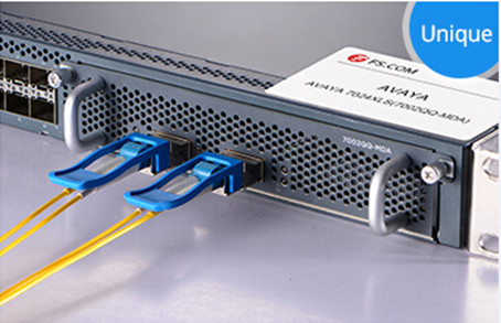
QSFP+ is featured with various advantages like delivering excellent high speed optical/electrical performance coupled with low power dissipation. In addition, with bundled fiber cables and MPO connectors, the port density of QSFP+ modules is triple that of SFP+ modules. Moreover, the power consumption is reduced from 1000 mW maximum per lane for SFP+ to 375 mW maximum per lane for QSFP+. 40GBASE-iSR4 QSFP+ module like AFBR-79EIDZ is not only 40Gb Ethernet compliant, but also inter-operable with any 10GBASE-SR compliant transceiver at link distances up to 100 meters over OM3 multimode fiber. The letter "i†in 40GBASE-iSR4 QSFP+ refers to the ability of inter-operation. AFBR-79EIDZ see in Figure 1 is Avago 40GBASE-iSR4 QSFP+ transceiver available on the market. Just as any other modules, this Avago QSFP+ iSR4 is designed to be fully compatible with the 40GBASE-SR4 specification. It’s capable of inter-operating with legacy 10GBASE-SR transceivers.
40GBASE-iSR4 QSFP+—an Cost-Effective Solution
40GBASE-iSR4 QSFP+ transceiver was released to tackle the issue of an overload condition when connecting a 40GBASE-SR4 transmitter to a 10GBASE-SR receiver. It is intended to be fully compliant to the 40GBASE-SR4 specification but with a lower maximum transmit optical output power. The maximum specified output power has been lowered from +2.4 dBm to -1 dBm allowing it to interface with 10GBASE-SR receivers without fear of overload.
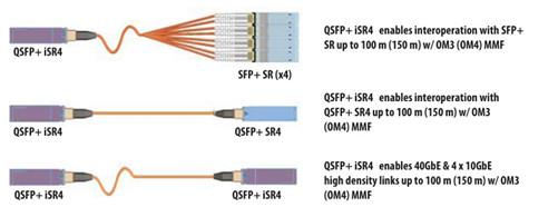
The VCSEL design combined with superior laser programming and control algorithms allow for a reduction in the module maximum specified optical output power without compromising any of the module high speed electro-optic performance. And the result (see in Figure 2) is a fully compliant 40GBASE-SR4 module like QSFP-40G-SR4 which can interoperate with legacy 10GBASE-SR transceivers. For further understanding of the 40GBASE-iSR4 optics, it is advisable for you to take a glance at the development of it.
Standardization of 40GBASE-iSR4
The release of IEEE 802.3ba-2010 standard for 40G Ethernet specifies the optical and electrical requirements for various physical layer link implementations. The 40GBASE-SR4 PMD (physical medium dependent) variant defines a 4-lane parallel optical interconnect for operation over OM3 multimode fiber with transmission distance up to 100 meters. Each of the four lanes works at a data rate of 10.3125 Gbps which is the same serial bit rate that was defined for 10G Ethernet links.
The 40GBASE-SR4 PMD addresses the need for 40Gbps interconnects in the data center. It takes advantage of the widely-deployed and low-cost 850nm VCSEL (vertical cavity surface emitting laser) technology. Because each of the 4 lanes in 40GBASE-SR4 have the same serial bit rate of 10G Ethernet link, there is an opportunity for switching hardware vendors to utilize 40GBASE-SR4 as 4 separate 10G Ethernet interconnects.
Challenge Hindering the Development
The standard of 40GBASE-SR4 provides an opportunity to further address the growing need for bandwidth. It is not defined to be backward compatible with the preceding 10G Ethernet short reach interconnect standard. Although both 40G Ethernet and 10G Ethernet included a PMD definition for short reach VCSEL based optical links operating at 10.3125 Gbps per lane, interoperability cannot be guaranteed.
The following analysis of 40GBASE-SR4 and 10GBASE-SR specifications tells why inter-operability cannot be guaranteed over all specified operating conditions.
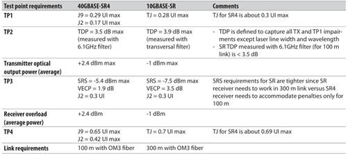
From the above chart, we could see that many of the transmitter and receiver specifications governing the 10GBASE-SR standard are equal or more stringent than those for 40GBASE-SR4 standard. This is not surprising because the 40GBASE-SR4 specification is written to cover transmission links up to 100 meters, while the 10GBASE-SR specification is intended to satisfy a maximum transmission link length of 300 meters over OM3 multimode fiber. Except the distance, the main specification gap preventing guaranteed inter-operability relates to receiver overload.
Summary
40GBASE-iSR4 QSFP+ proves itself as a suitable solution for designers to mount their network capacity. QSFP+ iSR4 optics is able to support standard 40G Ethernet links up to 100 meters over OM3 and 10GBASE-SR links over the same distances.
Posted by: angelina at
03:45 AM
| No Comments
| Add Comment
Post contains 881 words, total size 7 kb.
July 14, 2016
Ethernet cable is used to connect devices on local area networks (switch, router or hub), which is one of the most popular forms of fiber jumper cables used on wired networks. Ethernet cables are typically classified into sequentially numbered categories based on different specifications, such as cat5, cat5e, cat6, etc. What are the differences between these category Ethernet cable and how can you know when to use unshielded, shielded, stranded, or solid cable? This article will help you decide.
Category Ethernet Cable Difference
The Cat3, Cat4, Cat5, Cat5e, Cat6, and Cat7 are the abbreviation for the category number that defines the performance of UTP (Unshielded Twisted Pair) type of cable used for Ethernet wiring outlined by the Electronic Industries Association (EIA) standards. The differences in these cable specifications is not easy to identify. However, as the category number gets higher, so does the speed and Mhz of the wire. The following image shows a comparison between Cat5, Cat6 and Cat6 UTP cables.
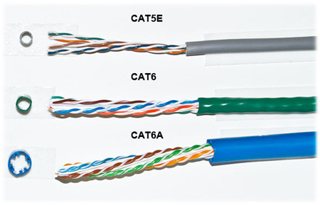
Besides the speed and hertz, there are two main physical differences between Cat5 and Cat6 cables, the number of twists per cm in the wire, and sheath thickness. It is known that cable twisting length is not standardized, but typically there are 1.5-2 twists per cm in Cat5e and 2+ twists per cm in Cat6. The amount of twists per pair is usually unique for each cable manufacturer. From the above picture, you can see that no two pairs have the same amount of twists per inch. And Cat5e cable has the thinnest sheath, but it also was the only one with the nylon spline. The nylon spline can help eliminate crosstalk, the thicker sheath protects against near end crosstalk (NEXT) and alien crosstalk (AXT) which both occur more often as the frequency (Mhz) increases.
Nowadays Category 5 cable was mostly replaced with Category 5 Enhanced (Cat5e) cable which did not change anything physically in the cable, but instead applied more stringent testing standards for crosstalk. While Category 6 was revised with Augmented Category 6 (Cat6a) which provided testing for 500 Mhz communication (compared to Cat6’s 250 Mhz). The higher communication frequency eliminated alien crosstalk (AXT) which allows for longer range at 10 Gb/s.
Shielded (STP) vs. Unshielded (UTP)
All Ethernet cables are twisted pair, but they are created equally. Telecom vendors rely on shielding to further protect the Ethernet cable from interference, thus the shielded twisted cable (STP) is more suitable for area with high interference and running cables outdoors or inside walls. Unshielded twisted pair however, can easily be used for cables between your computer and the wall. Technically the picture below shows a Screened STP cable (S/STP).
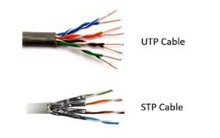
There are different methods to shield an Ethernet cable, but typically it involves putting a shield around each pair of wire in the cable. This protects the pairs from crosstalk internally. Manufactures can further protect cables from alien crosstalk but screening UTP or STP cables.
Solid vs. Stranded
Solid or stranded refer to the actual copper conductor in the pairs. Of an Ethernet cable. Solid conductor uses 1 solid wire per conductor, so in a 4 pair (8 conductor) roll, there would be a total of 8 solid wires. Stranded conductor uses multiple wires wrapped around each other in each conductor, so in a 4 pair (8 conductor) 7 strand roll, there would be a total of 56 wires.
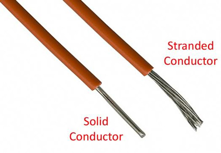
Each type of conductor (see in the above picture) can be utilized in different applications. Stranded cable is more flexible and should be used at your desk or anywhere you may be moving the cable around often. Solid cable is not as flexible as stranded cable, but more durable which makes it ideal for permanent installations as well as outdoor and in walls. Stranded wire are generally made with patch leads with connectors on the either end like LC to SC patch cord.
Conclusion
Due to the electrical transmission characteristics, a single Ethernet cable like an electric power cord, can extend only limited distances. At the end of the article, you may know when to choose STP, UTP, stranded or solid cables. Note that if you're cabling a mission critical system or you want your network to be future proof, go for the CAT6 cables, but for the average home or small office network CAT5 or CAT5e will be just fine.
Posted by: angelina at
08:28 AM
| No Comments
| Add Comment
Post contains 727 words, total size 6 kb.
July 12, 2016
Fiber optics, with its high bandwidth capacities and low attenuation characteristics, is considered to be the ideal building equipment in the telecommunication field. Depending on the type of application and the reach to be achieved, various types of optical fiber may be considered and deployed. This article is devoted to provide solutions to the questions about fiber optic cables. After going through the whole passage, you might form a basic understanding of optical cables.
What Is an Optical Fiber?
Core and cladding are the two main elements of an optical fiber. The core as shown in the image below, is the axial part of the optical fiber made of silica glass, which is the light transmission area of the fiber. The cladding is the layer completely surrounding the core. The refractive index of the core is higher than that of the cladding, so that light in the core strikes the interface with the cladding at a bouncing angle, gets trapped in the core by total internal reflection, and keeps traveling in the proper direction down the length of the fiber to its destination.
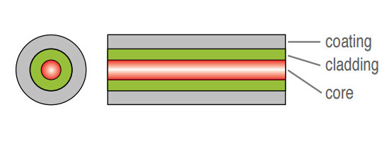
There is usually another layer, called a coating surrounding the cladding that typically consists of protective polymer layers applied during the fiber drawing process, before the fiber contacts any surface. As we all known, the most typical types of fiber optic cable are MM fiber patch cords and single mode fiber optic cables.
How Do Fiber Optics Work?
Fiber optics use light pulses to transmit signals from one end to another. Light passes through the optical cable, bouncing off the cladding until it reaches the other end of the fiber channel, which is called total internal reflection. The diameter of the core corresponds directly with the angle of reflection.
As this diameter increases, the light requires more reflections and a greater amount of time to travel a given distance. For example, single mode fiber optic cable has a smaller diameter core which makes itself suitable for long distance, higher bandwidth runs. Multimode fiber, however, has a larger diameter core and is more commonly used in shorter cable runs.
What You Need to Know About Optical Fiber?
Attenuation and WavelengthLight is gradually attenuated when it is propagated along the fiber. The attenuation value is expressed in dB/km. It is a function of the wavelength (λ), meaning that the operating wavelength to transmit a signal in an optical fiber is not any wavelength. It corresponds to a minimum of attenuation.
The typical operating wavelengths that light sources have been developed for are 850 nm and 1300 nm in multimode, and 1310 nm and 1550 nm in single mode. For a 850 nm operating wavelength, there is a 3dB light attenuation after 1 km propagation. 3 dB means that half of the light has been lost.
Bandwidth
Bandwidth is a measure of the data-carrying capacity of an optical fiber. For example, a fiber with a bandwidth of 500 MHz.km (Mega-hertz kilometer) can transmit data at a rate of 500 MHz along one kilometer. Bandwidth in single mode fibers is much higher than in multimode fibers.
How to Link Two Optical Fibers?
Fusion SpliceThis operation usually needs a fusion splicer to accomplish the process. In this method, optical technician directly links two fibers together by welding with an electric arc, by aligning best possible both fiber cores. Compared with other method, this linking method is fast and relatively simple to make. And the light loss generated by the welding, due to an imperfect alignment of the cores, remains very weak.
However, just as the coin has two sides, this link method has drawbacks. In spite of a protection of fusion by a heat-shrinkable tube, this type of link is relatively fragile. It is a permanent link. What’s worst, the fusion splicer is usually very expensive.
Use of Connectors
In this case, it is necessary to terminate a connector at each end of the fibers to be connected. The two fibers can then be connected by connecting the two connectors together. The following picture shows a SC fiber patch cord.
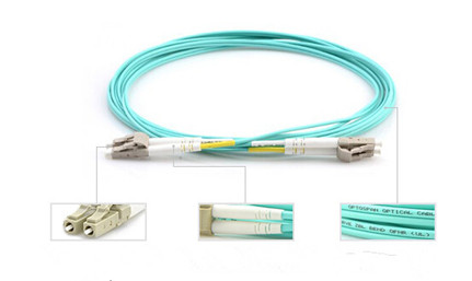
Just as the following picture shows, this type of connection is robust. The type of connector can be chosen according to the application field of the system. Unlike fusion splice, this connection is removable. It is possible to connect and disconnect two fibers hundreds to thousands times without damaging the connectors. But the implementation is longer than fusion, and requires an experiment as well as specific tools. Furthermore, the light loss due to connection is higher than in the splicing solution.
Why to Choose Fiber Optics?
The main advantages of fiber optics are the followings:- Lower loss: Optical fiber has lower attenuation than copper conductors, allowing longer cable runs and fewer repeaters.
- Increased bandwidth: The high signal bandwidth of optical fiber provides a significantly greater information-carrying capacity. Typical bandwidths for multimode fibers are between 200 and 600 MHz.km, and > 10 GHz.km for singlemode fibers. Typical values for electrical conductors are 10 to 25 MHz.km.
- Immunity to interference: Optical fibers are immune to electromagnetic and radio frequency interference and also emit no radiation themselves.
- No detection: Standard fiber optic cables are dielectric, so they cannot be detected by any type of detector.
- Electrical isolation: Fiber optics allows to transmit information between two points at two different electrical potentials, and also next to high voltage equipments.
- Decreased size and weight: Compared to copper conductors of equivalent signal-carrying capacity, fiber optic cables are easier to install, require less duct space, and weight about 10 to 15 times less.
Conclusion
The Internet nowadays is largely based around optical fiber. For those who do not understand fiber optics, they will have confusion and misconceptions when working with fiber optic networks. This article probably will not make you an optical engineer, but it will guide you to touch on a little bit of every topics, from the theoretical to the practical even if you aren’t designing optical networks.
Posted by: angelina at
07:54 AM
| No Comments
| Add Comment
Post contains 999 words, total size 8 kb.
July 07, 2016
Optical technology nowadays has made huge progress to meet the growing requirement for high-density multifiber applications in telecommunication field. Fiber optic splitter, as an indispensable equipment for fiber optic network, enables signals on an optical fiber to be distributed among two or more fibers. Optical cable splitter typically can be divided into FBT (Fused Biconical Taper) splitter and PLC (Planar Lightwave Circuit) splitter. Each type has advantages and disadvantages when deploying them in a passive optical network. This article will guide you to form a basic knowledge about fiber optic splitter, especially FBT splitter and PLC splitter.
Fiber Optic Splitter
Optical splitter, also known as a beam splitter, is based on a quartz substrate of an integrated waveguide optical power distribution device, which is used to split the fiber optic light evenly into several parts at a certain ratio. Since splitters contain no electronics nor require power, they are an integral component and widely used in most fiber optic networks. The diagram below shows how light in a single input fiber can split between four individual fibers (1x4).
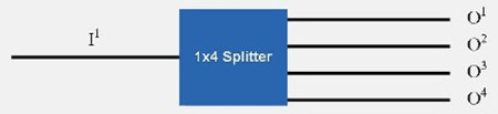
Optical splitters are manufactured commonly in two types according to its working principle—FBT (Fused Biconical Taper) splitter and PLC (Planar Lightwave Circuit) splitter. Splitters can be built using a variety of single mode fiber patch cables and multimode optical fibers and with most connector types for various applications.
FBT Splitter—FBT is a traditional technology that two fibers are typically twisted and fused together while the assembly is being elongated and tapered. The fused fibers are protected by a glass substrate and then protected by a stainless steel tube, typically 3mm diameter by 54mm long. FBT splitters are widely accepted and used in passive optical networks, especially for instances where the split configuration is not more than 1×4. The slight drawback of this technology is when larger split configurations such as 1×16, 1×32 and 1×64 are needed. The following picture shows a FBT splitter with a split configuration of 1×2.
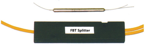
PLC splitter—A PLC splitter is a micro-optical component based on planar lightwave circuit technology and provides a low cost light distribution solution with small form factor and high reliability. It is manufactured using silica glass waveguide circuits that are aligned with a V-groove fiber array chip that uses ribbon fiber. Once everything is aligned and bonded, it is then packaged inside a miniature housing. PLC Splitter has high quality performance, such as low insertion loss, low PDL (Polarization Dependent Loss), high return loss and excellent uniformity over a wide wavelength range from 1260 nm to 1620 nm and have an operating temperature -40°C to +85°C. The following picture shows a PLC splitter connected with LC LC single mode patch cord.
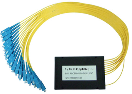
Advantages and Disadvantages of FBT and PLC splitters1. FBT—Fused Biconical Splitter
FBT splitter is one of the most common splitters, which is widely accepted and used in passive networks. FBT splitter is designed for power splitting and tapping in telecommunication equipment, CATV network, and test equipment.
Advantages
- The product is well-known and is easy to produce, thus reducing cost of production.Splitter ratios can be customized.
- Can work on three different operating bands (850nm, 131 Onm, and 1550nm).
Disadvantages
- Restricted to its operating wavelength.
- Because of errors in equality insertion loss, the maximum insertion loss will vary depending on the split and increase substantially for those splits over 1:8.
- Because an exact equal ratio cannot be ensured, transmission distance can be affected.
- High temperature dependent loss (TDL). The operating temperature range is 23 °F- 167 °F. Any changes in temperature can affect the insertion loss.
- The larger the split, the larger the encapsulation module.
- Susceptible to failure due to extreme temperatures or improper handling.
2. PLC—Planar Lightwave Circuit Splitter
PLC splitter is a hot research at home and abroad today, with a good prospect of application, which is used to distribute or combine optical signals. It is based on planar lightwave circuit technology and provides a low cost light distribution solution with small form factor and high reliability.
Advantages
- Suitable for multiple operating wavelengths (1260nm–1650nm); unstinted.
- Equal splitter ratios for all branches.
- Compact configuration; smaller size; small occupation space.
- Good stability across all ratios.
- High quality; low failure rate.
- Complicated production process.
- Costlier than the FBT splitter in the smaller ratios.
Conclusion
Similar in size and outer appearance, PLC and FBT splitters provide data and video access for business and private customers, but internally the technologies behind these types vary, thus giving service providers a possibility to choose a more appropriate solution.
Posted by: angelina at
02:24 AM
| No Comments
| Add Comment
Post contains 755 words, total size 7 kb.
July 01, 2016
Fiber optical cable is the composite material, typically consists of a hair-thin glass used to transmit pulses of light instead of electrical signals. Thus the termination must be much more precise. Compared with copper cables end with RJ connectors, fiber optic connectors must align microscopic glass fibers perfectly to make metal to metal contact. There are many different types of fiber connectors, they share similar design characteristics, such as LC to LC patch cord, single mode LC to ST fiber patch cable, single mode fiber ST to SC patch cord, single mode fiber cable with LC connector, etc. Nowadays most cables are ended with the same connector, which poses a problem for users to sort through cables and connectivity options. That’s why this article is provided here to help out the illustration of fiber optics and optical connectors.
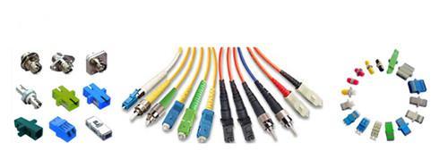
Internal Structure of Optical Connector
Fiber optic connector terminates the end of fiber optic cable, enabling quicker connection and disconnection than splicing. As noted before, optical connector has to be aligned properly to the microscopic glass fibers completely in order to allocate for communication. There are three major components of a fiber connector: the ferrule, the connector body, and the coupling mechanism.
- Ferrule
It is a thin structure that is actually used to holds the glass fiber, which has a hollowed-out center that forms a tight grip on the fiber. Ferrules are usually made from ceramic, metal, or high-quality plastic, and typically will hold one strand of fiber.
- Connector Body
This is a plastic or metal structure that holds the ferrule and attaches to the jacket and strengthens members of the fiber cable itself.
- Coupling Mechanism
This is a part of the connector body that holds the connector in place when it gets attached to another device. It may be a latch clip, a bayonet-style nut, or similar device.
Different Types of Fiber Optic Connectors
To sum up, there are nearly 100 fiber optic connectors on the market, but only a few are available that was lower loss, lower cost, easier to terminate. Optical connectors like LC connector, SC connector, ST connector, FC connector, RJ45 connector, MT-RJ connector are the representative that will be present to you.
- SC Connector
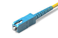
SC or square connector, was developed by Nippon Telegraph and Telephone on the market, slowly grew in popularity as manufacturing cost went down. Now it is becoming increasingly popular in single-mode fiber optic cable, analog CATV, GPON, GBIC. SC is a snap (push-pull coupling) connector with a 2.5mm ferrule diameter that operates on the standard IEC 61754-4. The connector’s outer square profile together with its snap coupling mechanism that allows greater connector packaging density in instruments and patch panels. The SC fiber patch cord is ideally suited for datacoms and telecoms applications including point to point and passive optical networking.
- LC Connector
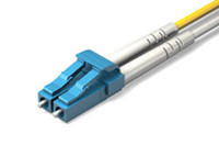
LC or Lucent Connector, is a push-pull, small form factor connector that uses a 1.25mm ferrule, half the size of the SC. Due to the combination of small size and latch feature, LC connector is ideal for high-density connections and usually utilized in SFP, SFP+, XFP, and single-mode QSFP+ transceivers. Along with the development of LC compatible transceivers and active networking components, it will continue to grow in the FTTH arena.
- FC Connector
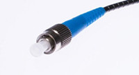
FC or Ferrule Connector., is a round, threaded fiber optic connector that was designed by Nippon Telephone and Telegraph in Japan. The FC connector is applied for single-mode fiber and polarization-maintaining optic fiber. The FC is a screw type connector with a 2.5mm ferrule, which was the first fiber optic connector to use a ceramic ferrule. However, FC is becoming less common and gradually replaced by SC and LC connectors because of its vibration loosening and insertion loss.
- ST Connector
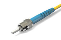
ST or Straight Tip, was developed by AT&T shortly after the arrival of the FC. They may be mistaken for one another, but ST uses a bayonet mount other than a screw thread. And you have to make sure SC connectors are seated properly owing to its spring-loaded structure. SC is mainly used in multimode fiber optic cable, campuses and buildings.
- RJ-45 Connector
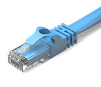
RJ-45 connectors are physically wider than the RJ-11/12 connectors used for telephone. In network applications, RJ-45 cable assemblies are used to connect from a patch panel to a network switch, and also to connect a computer's NIC to a data port.
- MT-RJ Connector
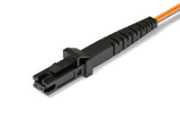
The MTRJ connector closely resembles an RJ-style modular plug, even getting part of its name from the resemblance. It is covered in the TIA connector intermateability standard FOCIS-12 (TIA-604-12). MT-RJ is a duplex connector with both fibers in a single polymer ferrule. It uses pins for alignment and has male and female versions. Multimode only, field terminated only by prepolished/splice method.
Conclusion
Whether you are about to install a new fiber optic network, or perhaps you are maintaining on an existing one, you are supposed to have a basic knowledge about fiber optics and optical connector. This article simply illustrates the most commonly used fiber optic connectors on the market to help you sort through the optical connectors.
Posted by: angelina at
03:16 AM
| No Comments
| Add Comment
Post contains 851 words, total size 7 kb.
June 29, 2016
Optical fiber is the ideal transmission medium for light signals in contrast to copper cable, and it rarely needs amplification. When the signals carried by light travel through the core of fiber jumper cables, the strength of the light will be weaker, as it’s impossible not to incur degradation of light over the length of the network connection. It is inevitable, but if the signal becomes too weak, it will affect the performance of the fiber optic network. So understanding and tackling these losses is a critical part of network installation and testing.
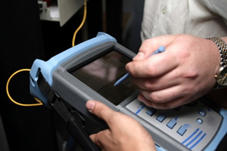
This loss of light power is generally called fiber optic loss or attenuation (measured in dB). High-quality single-mode fiber will often exhibit attenuation. The cause of fiber optic loss located on two aspects: internal reasons and external causes of fiber optic, which we often use the term insertion loss (IL) and return loss (RL) to describe it.
Insertion Loss
Insertion loss refers to the measurement of light that is lost between two fixed points in the fiber, which usually occurs when optical fibers are spliced together, connected, or sent through additional passive network components. It is often attributed to misalignment, contamination, or poorly manufactured connectors (ferrules) and has long been used to advocate fusion splicing. However, in reality, the attenuation difference between fusion splicing and manual connections is marginal (less than 0.1 dB).
Optical connectors might be most likely the cause of high IL, but it’s unfair to think of them as the only culprit. I have watched a splice engineer perform a perfect fusion splice onto a mass-produced, low-cost commodity pigtail, because the Optical Network Terminal (ONT) called for an SC or LC connector. In reality, we can manage connector losses by stipulating the IL standards of the cables we buy, and training installers to keep things clean. Reducing the number of components within the network also logically lowers the insertion loss.
Furthermore, micro and macro-bending (see in Figure 2) may attribute to significant IL, or cracks to the glass caused by over-tensioning (pulling) or by crush and impact damage. This is often the worst kind of attenuation because it takes time to develop and is much more difficult to pinpoint.
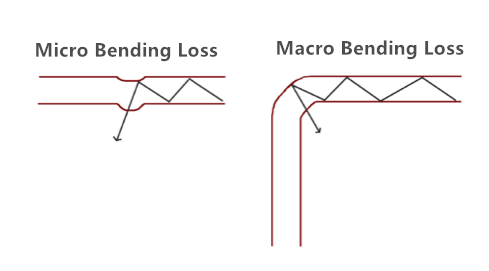
Another reason for fiber seemingly exhibiting high IL in fiber to the home (FTTH) networks is the route of the cable itself. For example, a fiber might travel 10km from the OLT to the curb and lose less than 1dB, and then go on to lose three times as much in the next 100 meters. Multi dwelling units (MDUs) are a great example of complex fiber routes, and it is especially important to protect bend radii, such as with dedicated raceways or microducts. Fiber can quite easily become tightly coiled or kinked during installation; even bend insensitive G657A1 fiber coiled just once to 20mm diameter will see as much as 0.2dB loss. Coiled twice at 20mm 0.4dB, three times and... you get the picture.
Return Loss
Fiber Return loss also have great impacts on the network’s performance (see in Figure 3). It refers to the amount of signal reflected back towards the source due to an impedance mismatch effectively, if this is too high, the laser within the network may stop transmitting correctly. Many systems can cope with 40dB return loss (RL), equivalent to 0.01 per cent of the power being sent back. FTTH, however, is more demanding, and RL cannot be more (lower) than -60dB, sometimes higher.
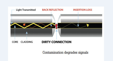
Cable, specifically, can show high RL if a gap exists (such as fiber undercut) or if the fiber is broken. Contamination, torsion, strain or poorly seated connectors can also lead to high return losses. Therefore, it is important that networks are tested to ensure that there aren’t any unexpectedly high RL figures that indicate problems with equipment or fibers. To achieve these ultra-low RL figures, optical connectors must have angled ferrules (APC).
Insertion loss and return loss are not the same thing and, therefore, need to be measured separately. Measuring the RL on the fiber will pinpoint the issue as the response would be unexpectedly high. The complexity of fiber networks, and the need to measure optical losses, can potentially lead to confusion. However, careful planning, use of high-quality components and a focus on testing will enable installers to deliver high-speed connections that perform well over the long term. Here are five easy tips for reducing your losses.
Tips for Reducing Fiber Loss
1. Minimize tight bends that cause light to refract through the fiber cladding. If you need to coil fiber, keep the radius as large as possible.2. Clean connector ferrules little and often - especially before and after testing—and always use the right tools and consumables.3. Decide which is higher: your "power loss" budget or your cable inventory budget. Buying cheap fiber can create larger costs further down the line.4. Avoid any undue stress on the fiber, particularly during installation. Push where possible and if a cable needs pulling, do not exceed the cable’s maximum tensile load.5. Minimize the number of splices or connections in your network; if it means better planning or more innovative drop cables, the investment is probably well worth it.
Conclusion
The power or strength of the signal is typically higher at the head end of the optical network, but lower at the other end because of the fiber loss. To ensure smooth fiber optic transmission, fiber optic loss must be decreased. You can follow the above tips to help you out.
Posted by: angelina at
03:12 AM
| No Comments
| Add Comment
Post contains 919 words, total size 7 kb.
June 24, 2016
The common 40GBASE-LR4 QSFP+ optical transceivers that are available on the market are QSFP-40GE-LR4, QSFP-40G-LR4, QSFP-40G-LR4-S and WSP-Q40GLR4L. They are all compatible with 40GBASE-LR4 standard, but differ with each other. Since I have already explained the difference between the above 4 optical transceivers, I will not go further about these topic today. Except for the different 40GBASE-LR4 QSFP+ transceivers types, there are also two links for 40GBASE-LR4 standards. One is coarse wavelength division multiplexing (CWDM). The other is parallel single-mode fiber (PSM). In this article, these two links of 40GBASE-LR4 QSFP+ transceivers will be introduced to you.
40GBASE-LR4 CWDM QSFP+ Transceiver
The 40GBASE-LR4 CWDM QSFP+ transceiver (likeQSFP-40GE-LR4) is compliant to IEEE P802.3ba 40GBASE-LR4 standard. This QSFP module supports link lengths of up to 10km over single-mode fiber (SMF) with duplex LC connectors. This transceiver converts 4 inputs channels of 10G electrical data to 4 CWDM optical signals by a driven 4-wavelength distributed feedback (DFB) laser array, and then multiplexes them into a single channel for 40G optical transmission, propagating out of the transmitter module from the SMF. Reversely, the receiver module accepts the 40G CWDM optical signals input, and demultiplexes it into 4 individual 10G channels with different wavelengths. The central wavelengths of the 4 CWDM channels are 1271, 1291, 1311 and 1331 nm (defined as members of the CWDM wavelength grid in ITU-T G694.2). Each wavelength channel is collected by a discrete photo diode and output as electric data after being amplified by a transimpedance amplifier (TIA).
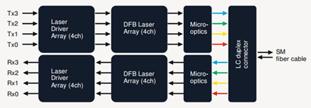
40GBASE-LR4 PSM QSFP+ Transceiver
Unlike CWDMQSFP+ transceiverusing a LC connector, PSM QSFP+ is a parallel single-mode optical transceiver with an MTP/MPO fiber ribbon connector. It also offers 4 independent transmit and receive channels, each capable of 10G operation for an aggregate data rate of 40G on 10km of single-mode fiber. Proper alignment is ensured by the guide pins inside the receptacle. The cable usually cannot be twisted for proper channel to channel alignment. In terms of a PSM QSFP+, the transmitter module accepts electrical input signals compatible with common mode logic (CML) levels. All input data signals are differential and internally terminated. The receiver module converts parallel optical input signals via a photo detector array into parallel electrical output signals. The receiver module outputs electrical signals are also voltage compatible with CML levels. All data signals are differential and support a data rates up to 10.3G per channel.
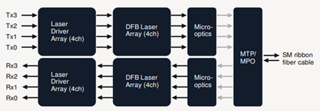
Compare 40GBASE-LR4 CWDM QSFP+ With 40GBASE-LR4 PSM QSFP+ Transceiver
As noted before, 40GBASE-LR4 CWDM QSFP+ transceivers use a duplex LC connector via 2 optical single-mode fibers to achieve 40G without making any changes to the previous 10G fiber cable plant. However, 40GBASE-LR4 PSM QSFP+ transceivers use an MTP/MPO fiber ribbon connector via 8 optical single-mode fibers to reach 40G. Obviously, CWDM QSFP+ is a more cost-effective solution for 40G connectivity.
What’s more, in terms of the inner structure of an optical transceiver module, PSM QSFP+ uses a single uncooled CW laser that splits its output power into four integrated silicon modulators, which is much inexpensive than CWDM QSFP+. Besides, its array-fiber coupling to an MTP connector is relatively simple. A picture comparing the key differences between CWDM and PSM is shown below:

Additionally, the caveat is that the entire optical fiber infrastructure within a data center, including patch panels, has to be changed to accommodate MTP connectors and ribbon cables, which are more expensive than conventional LC connectors and regular SMF cables. Not to mention that cleaning MTP connectors is not a straightforward task.
Conclusion
PSM and CWDM are the two links of 40GBASE-LR4 QSFP+ transceivers. Both of them can support a link distance of 10km. However, 40GBASE-LR4 CWDM QSFP+ are more common than 40GBASE-LR4 PSM QSFP+ because of its performance and low cost. Fiberstore offers a wide brand compatible 40G CWDM QSFP+ transceivers. Each of our fiber optic transceivers has been tested to ensure its compatibility and interoperability.
Posted by: angelina at
02:22 AM
| No Comments
| Add Comment
Post contains 655 words, total size 6 kb.
June 15, 2016
In such a digital world, human beings are keen on developing technologies to facilitate daily lives. In order to process and store tons of information, many different forms of storage like CD-ROM, USB Key, and DVD has been developed. However, the above devices can only store limited data, which is not adequate for the information explosion. Thus cloud computing, as an advanced storage solution, appears on the stage. So how to achieve cloud computer? Different voices with different opinions emerge, but from a technician’s standpoint, a reliable cabling connectivity or fiber jumper is key to cloud computing. Whether you agree with my opinion or not, the following article will provide some detailed information about it to help you find out the answer.
What Is Cloud Computing?
The "Cloud†in the term cloud computing, describes an image of the complex infrastructure, covering all the technical details. Obviously, the cloud computing has nothing to do with the weather "cloudâ€. It is just an analogy to give it a body to imagine. Cloud computing is a model for computing transforming. In this model, data and computation are operated somewhere in a "cloudâ€, which is some collection of data centers owned and maintained by a third party. This enables ubiquitous, convenient, on-demand network access to a shared pool of configurable computing resources that can be rapidly provisioned and released with minimal management effort or service provider interaction.
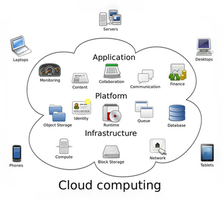
There are public cloud, private public and hybrid cloud. When a cloud is made available in a pay-as-you-go manner to the general public, we call it a public cloud. And when the cloud infrastructure is operated solely for a business or an organization, it is called private cloud. A composition of public and private cloud is called hybrid cloud. A hybrid cloud integrates the advantages of public cloud and private cloud, where private cloud is able to maintain high service availability by scaling up their system with externally provisioned resources from a public cloud when there are rapid workload fluctuations or hardware failures.
Optical Fiber Is the Key to Cloud Computing
In the "cloud†network, subscribers’ terminals are simplified into a pure and single device with only input and output functions but meanwhile utilize the powerful computing and processing functions from the "cloudâ€. This means that the terminal must have a very fast connection, because the simple terminal means fast network and powerful platform requirement, where "pipes†are put forward higher requirement. Thus, fiber is the ideal "pipe†for cloud computing. The following image shows the evolution of memory storage.

In fact, computer applications, software and even file storage now reside on the Internet or in the "cloudâ€. Yet another driving force is mobile Internet traffic, which relies heavily on cloud computing. It is said that there is over 1 Exabyte of data currently stored in the cloud. And this number is growing exponentially every day. The greatest thing that will limit your ability to work seamlessly in the "cloud†is your Internet connection. Thus, to access the tremendous amounts data, we need fiber networks that can carry Terabits—one trillion bits per second. Fiber jumper cables can offer more available bandwidth and speed which meets the demands of the "cloudâ€. Obviously, no technology is more effective at meeting that challenge than fiber at present.
What’s more, FTTH infrastructure is expected as a solution to meet the growing demands for high bandwidth. It brings fiber optic connections directly into homes, allowing for delivery speeds up to a possible 100 Mbps, or even more. These speeds open the door to a variety of new services and applications for residential, business and public service markets. The relationship between FTTH and cloud computing is subtle. FTTH encourages the growth of cloud computing with its benefits. And cloud computing may in turn drives the development of FTTH.
Conclusion
As cloud computing market continues to mature, current and potential information technology capabilities offers many benefits to our lives. However, just like other new technology advancement, cloud computing also faces many challenges, which requires all of us to form thoughts on the strengths and downfalls of the technology. Fiber optic cable, as an indispensable component of network infrastructure, plays a vital role in cloud computing.
Posted by: angelina at
02:34 AM
| No Comments
| Add Comment
Post contains 709 words, total size 6 kb.
30 queries taking 0.167 seconds, 115 records returned.
Powered by Minx 1.1.6c-pink.

