



May 31, 2016
Fiber to the home (FTTH) developments clearly influence the demand for today’s home purchases. Developers and home builders recognize the need for reliable high-speed broadband communications. Thus they should seize the opportunity to design FTTH network during the design and construction of the development. In fact, deploying FTTH in a new development is at cost similar with deploying copper at the same location. But the long-term benefits stemming from fiber-ready infrastructure further catch people’s attention. Unlike coax and xDSL, fiber is more than just fast. So why implement FTTH development? The following article will give a further illustration of the reasons.
Fast Bandwidth
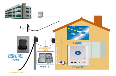
Cable modem and xDSL helped residential broadband get off the ground. Now, however, the sheer speed of fiber overcomes bandwidth limitations of coax and copper. To illustrate, rising consumer demand for big-screen LCD displays can chew up 19 Mbps of bandwidth per channel. In addition, broadband connections are constantly clamoring for more band-width, both upstream and downstream. With busier lives, families want high-speed broad-band communications to transfer e-mail, digital photos and Internet files and they also want entertainment options such as time-sensitive, interactive video gaming that requires bi-directional bandwidth capability. With the typical household having three or more TVs and the ferocious appetite of broadband vying for capacity, it is easy to see that an abundant supply of fiber bandwidth must be included in the design and construction of the development. Figure 1 shows the basic FTTH architecture.
Reliable Capacity
Noisy channel conditions, inclement weather, environmental clutter such as buildings and trees, corroded connections and distance limitations can all impact the reliable delivery of residential broadband. However, the FTTH network access architecture is immune to all of these conditions so there is virtually no downtime. In addition, economical battery backup at the residential NID automatically kicks in when line power is interrupted. Furthermore, FTTH assures the demanding subscriber that they always receive the high-speed broadband capacity that they are paying for, both upstream and downstream, no matter how loaded the access network may be. This built-in reliability is no longer the exception but rather what the homeowner now expects and the builder’s life becomes much easier with satisfied homeowners.
Easy Deployment
Making the optical channel ready for signals once required a skilled technician to carefully splice fiber cables together. Today, the success of FTTH is no longer tied to fiber splicing in the field. As already alluded to, the distribution and drop segments of the FTTH network are easily deployed and intuitively connected. For example, the preterminated fiber drop can reduce subscriber connection time by up to 50 percent because it can be easily screwed into the terminal and the NID by an installer who does not need to know anything about fiber. In the distribution segment, the ease of deployment can shave off 80 percent of the deployment time, because once the terminal distribution system has been placed, homes are immediately ready to be connected into the network.
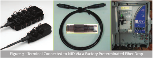
In addition, with FTTH, there is no need for high-voltage power supplies in the neighborhood. Manufacturers are also continuing to improve the appearance and reduce the size of fiber cabinets and terminals relative to the traditional copper products. Combined, this results in a much more aesthetically pleasing deployment than ever before.
Future Proofing
An FTTH network offers land developers an enviable return on their investment capital. Timely planning today can net thousands of dollars in profit. For example, if you invest $500 per home to deploy the fiber jumper and connecting hardware and the home then sells for $5,000 more than it would have otherwise, your investment just returned a handsome 1000 percent profit. That is easy math and easy money.
The return on fiber investment does not stop with its deployment, however. The network operator will also appreciate that robust, reliable and cost-effective FTTH network as they seriously consider their operational expenses. For example, an optical access network featuring segments that can, by design, be quickly connected together not only reduces the upfront deployment cost but also will reduce the amount of time required to turn up subscribers, test and troubleshoot the network. As the triple-play battle for the residential customer continues, a preterminated FTTH network can make the business case very enticing because it sets the network operator’s stage for reduced operational costs and additional revenue from advanced services such as home security and home networking.
Operationally, fiber drop cables are quickly and easily screwed into terminals and residential network interface devices (NID) across the country to save both time and money. Without these key advances in FTTH technology that reduce capital and operational costs, FTTH would continue to wrestle its competitors but now FTTH wins the access investment hands down.
Beneficial Solution
Modern day residential services like HDTV and high-speed broadband that enhance the quality of life in homes are being delivered via FTTH. Looking forward, FTTH residential developments ensure that advanced services such as telecommuting, telemedicine and distance learning will all be transparently realized. FTTH results in reduced commutes and environmental pollution, prolonged quality of life, and education, education, education. Broadband communications is a key element in an increasingly competitive global economy. With FTTH, the world will be better positioned for social and economic prosperity.
Summary
To sum up, FTTH deployment is unstoppable with all the positive impacts that fiber affords. If you are still waiting for service providers to install cable and manually turn up services, then you are left behind.
Posted by: angelina at
02:23 AM
| No Comments
| Add Comment
Post contains 913 words, total size 7 kb.
May 20, 2016
Ethernet as the networking standards, enables computers to locally connect to each other, which is the ultra-strong backbone to the many networks we use every day. Although most of the Ethernet market is still running around 1 Gbqs or 10 Gbqs, there is a strong interest in higher data rates. Many hardware vendors like Cisco, Finisar, Huawei and Brocade have recently announced support for 100 Gigabit Ethernet and telecom vendors around the world have also shown interest in launching 100G networks. All these events shows the sign of the advent of 100 Gigabit Ethernet in the commercial segment. However, is it necessary to move to 100G now? Or should the 100g migration be a smooth one just as the IEEE has made when moving to 40G? This article will highlight the reasons and solutions of upgrading to 100G.
Why Move to 100G?
- Most enterprises today are encouraging telecommuting and promote real-time, high-definition, high-quality voice and video solutions. All these require a huge bandwidth capacity. Additionally, 100G implementations offer an effective means to operate seamlessly within an existing 10G network infrastructure, avoid the need for additional optical amplifiers, dispersion compensators or regenerators. 100G is today’s choice to scale networks in a way that delivers the required capacity in the most efficient manner, readying the network for tomorrow’s bandwidth crunch.
- Another interesting point is the efficiency of 100G Ethernet compared to link aggregation that is used today. As of now, a 10 x 10G Ethernet link aggregation can not give a throughput of up to 100 Gbps. This limitation can be overcome with a true 100G connection which can give a 100Gbps bandwidth, thus allowing high capacity links to scale even further. Considering all these, if not this year or the next, 100G will be widely adopted soon.
- Last but not the least, the industry have come together in order to create a healthy 100G ecosystem, which will be beneficial for the entire community. This broad inclusion will result in a fast introduction of 100G solutions that will meet industry performance, size, cost, and power requirements. If the cost drive is right, once 100G is standardized and commercially available, network operators will quickly capitalize 40G investments and adopt 100G transmission for their future deployments.
Migrate to 100G with 100G Transceiver Modules
There are several form factors for supporting 100GbE including CFP, CFP2, CFP4, QSFP28 and CPAK. The following will make a clear introduction to all of them.
CFP Transceiver
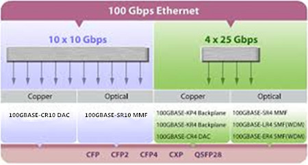
The CFP is the very first 100G transceiver for the transmission of high-speed digital signals, the C stands for the Latin letter centum (means 100). The CFP module was designed after the SFP interface, but is significantly larger to support 100 Gbqs using 10 x 10 Gbit/s lanes in each direction (RX, TX). The optical connection can support both 10 x 10 Gbit/s and 4 x 25 Gbit/s variants of 100 Gbit/s interconnects. There are four common types of CFP transceiver modules, such as 100GBASE-SR10 in 100 meter MMF, 100GBASE-LR10 and 100GBASE-LR4 in 10 km SMF reach, and 100GBASE-ER10 and 100GBASE-ER4 in 40 km SMF reach respectively.
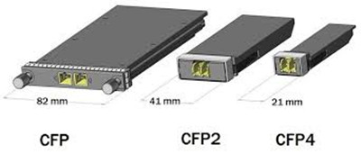
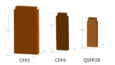
As improvements in technology have allowed higher performance and higher density, which drives the development of the CFP2 and CFP4 specifications. While CFP, CFP2 and CFP4 are electrical similar, they specify a form-factor of 1/2 and 1/4 respectively in size of the original specification. Note that CFP, CFP2 and CFP4 modules are not interchangeable, but would be inter-operable at the optical interface with appropriate connectors.
QSFP28 Transceiver
QSFP28 is the same footprint as the 40G QSFP+ module. Just as the 40G QSFP+ module is using four 10Gbps lanes, the 100G QSFP28 is implemented with four 25Gbps lanes. In all QSFP versions, both the electrical lanes and the optical lanes operate at the same speed, eliminating the costly gearbox found in CFP, CFP2, and the CPAK. The QSFP28 module has an upgraded electrical interface to support signaling up to 28Gbps signals, yet keeps all of the physical dimensions of its predecessor. As QSFP28 technology becomes even maturer, QSFP28 transceivers will become more and more popular in 100G optics market. The above image shows a QSFP-100G-SR4-S. it is Cisco 100GBASE-SR4 QSFP28 transceiver module.
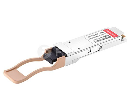
100GBASE-SR4 QSFP28 transceiver and 100GBASE-LR4 QSFP28 transceiver are the two main types of the QSFP28 transceivers. The former is specified to operate over multimode fiber (MMF) with the maximum link length of 70m on OM3 and 100m on OM4, while 100GBASE-LR4 QSFP28 is standardized to work through single-mode fiber (SMF), able to realize 10km link length.
QSFP28 vs. CFP
QSFP28 and CFP are the two common 100G optical transceivers available on the market. As noted before, CFP is the first-generation 100G transceiver. It is the common scene that QSFP28 makes an appearance and CFP takes a bow, which reflects the trend in the industry to aggressively bring 100GE density up and costs down. CFP4 is half the width of CFP2, which is half again the width of CFP. QSFP28 has the same footprint and faceplate density as QSFP+ and is just slightly smaller than CFP4. Theoretically, QSFP28 seems to have the density advantage over CFP4, but CFP4’s higher maximum power consumption gives it the advantage on longer reach optical distances. However, the CFP is much more expensive than QSFP28 and will not be used for lower speeds because of the high cost.
CPAK Transceiver
CPAK is another newcomer to supporting 100G network. This is a proprietary form factor from Cisco but the interfaces demonstrated are IEEE standards and will interoperate with the same interfaces supported by other form-factors. Together, these solutions will deliver the smallest form-factor, most efficient 100-Gbps optical transceiver portfolio in the industry. Cisco CPAK will be available in several IEEE-standard optical interfaces.
Conclusion
Within the next several years, 100G is doom to become the dominant backbone technology in terms of its high capacity over 10G and surpassing would-be high-speed contender 40G. Of course, we must count on the components and systems suppliers to build products that meet technical and economic requirements while allowing a smooth migration to the 100G infrastructure that is being put in operation today.
Posted by: angelina at
03:38 AM
| No Comments
| Add Comment
Post contains 1022 words, total size 8 kb.
May 18, 2016
The virtualized workloads, cloud applications, and big data services today are driving previously server and data center fabric to an unimagined level. The existing 1Gbqs or 10Gbqs are gradually overwhelmed by higher-bandwidth like 40Gbps or 100Gbqs. Thus high-capacity optical technology and cabling infrastructure are required to support those servers and applications for 40Gbps upgrading. However, it might be too costly to replace all your equipment for 40G transition. So this article will introduce a cost-saving solution to help you smoothly migrate to 40GbE with the use of 40G BiDi QSFP+ transceiver.
40G BiDi QSFP Transceiver Overview
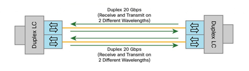
Bidirectional optical transceivers used for 40GBASE-SR-BD have the same 10-Gbps electrical lanes, which are then combined in the optical outputs, requiring two fibers with an LC connector interface. Each fiber simultaneously transmits and receives 20Gbps traffic at two different wavelengths. Figure 1 shows a electrical and optical lanes diagram of bidirectional optical transceiver. It can support link lengths of 100 meters and 150 meters, but on duplex LC OM3 and OM4 multimode fibers, which enables it use the existing 10 gigabit duplex MMF infrastructure for migration to 40 Gigabit Ethernet connectivity. Take QSFP-40G-SR-BD as an example, the Cisco QSFP 40Gbps BiDi transceiver supports link lengths of 100 and 150 meters on laser-optimized OM3 and OM4 multimode fibers, respectively. And this transceiver can also support 30m over OM2.
Difference Between 40GBASE-SR4 Parallel and Bidirectional Optical Transceivers
The IEEE standard 802.3ba released several 40Gbps based solutions, including 40GBASE-SR4 parallel optics solution for multimode fiber (MMF) and bidirectional 40Gbps transceiver. Unlike 40G BiDi QSFP transceiver, 40GBASE-SR4 parallel transceiver is simultaneously transmitted and received over multiple fibers. This transceiver has 10Gbps electrical lanes that are mirrored in the optical outputs and thus require eight fibers with an MTP connector interface. Each fiber either transmits (Tx) or receives (Rx) 10-Gbps traffic at a single wavelength.
While 40GBASE-SR Bi-Directional QSFP (see in Figure 2) has two 20Gbps lanes at two different wavelengths over a single MMF strand, enabling an aggregated 40Gbps link over a two-strand multimode fiber connection. It can support link lengths of 100 meters and 150 meters, but on duplex LC OM3 and OM4 multimode fibers, which enables it use the existing 10 gigabit duplex MMF infrastructure for migration to 40 Gigabit Ethernet connectivity.
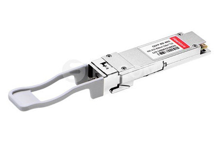
To sum up, this two-fiber 40Gbps Bidirectional (BiDi) multimode solution uses two different transmission windows (850 nm and 900 nm) that are transmitted bidirectionally over the same fiber, which will allow the use of same cabling infrastructure for 40 Gigabit Ethernet as was used for 1 and 10G Ethernet application. While the parallel multimode optical transceiver operates at a wavelength of 850nm. Additionally, the connector type was converted from the traditional 2-fiber LC duplex connector to a 12-fiber MTP connector.
Use Your Existing 10 Gigabit Ethernet Fiber for 40 Gigabit Ethernet
Whether your cable plant is structured or unstructured, 40G BiDi QSFP transceiver delivers significant savings and a smooth migration to 40 Gigabit Ethernet. For instance, in a structured cabling system, devices are connected directly with fiber cables within short distances in a data center network. The existing 10Gbps direct connections commonly use LC MMF fiber, 40GBASE-SR Bi-Directional QSFP therefore allows cable reuse, resulting in zero-cost cabling migration from direct 10Gbps connections to direct 40Gbps connections. It is the same case with the structured cabling system. Figure 3 shows 40Gbps structured cabling solutions with 40GBASE-SR Bi-Directional QSFP transceivers and the similar 10Gbqs structured cabling with 10GBASE-SR SFP+.
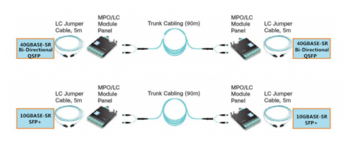
The BiDi transceiver enables the use of an existing 10 Gigabit Ethernet fiber plant infrastructure for 40 Gigabit Ethernet, delivering four times the bandwidth over the same fiber plant and up to 70% savings over other current solutions. QSFP 40 Gigabit Ethernet BiDi technology removes 40Gbps cabling cost barriers for migration from 10Gbps to 40Gbps connectivity in data center networks. It provides simpler and less expensive 40Gbps connectivity compared to other 40Gbps transceiver solutions. The Cisco QSFP BiDi transceiver allows organizations to migrate their existing 10Gbps cabling infrastructure to 40Gbps with little capital investment.
Conclusion
For building out new data centers, deploying 40 Gigabit Ethernet for aggregation and core is no longer an option but a requirement to meet today’s data demands. Designing your new fiber cable plant with 40 Gigabit Ethernet BiDi transceiver allows you to reduce your fiber requirements while future proofing your data center for 100 Gigabit Ethernet.
Posted by: angelina at
02:57 AM
| No Comments
| Add Comment
Post contains 728 words, total size 6 kb.
May 12, 2016
SFP optical transceiver is generally regarded as the most useful technological advancements of the telecom industry. This transceiver is less than half the width of the GBICs and created under the Multi-Source Agreement (MSA). SFP transceiver is hot-swappable, which is highly beneficial to network designers. What’s more, the smaller size and high performance enable the enterprises to cost-effectively migrate to Gigabit Ethernet. There are a number of small form pluggable (SFP) optical modules and network accessories to select from. Therefore, to save your troubles, this article elaborates three basic information of SFP transceiver module to make sure you have chosen the right one.
The Origin of SFP Optical Module
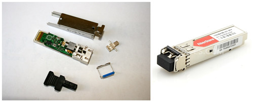
SFP transceiver modules are hot-pluggable module with LC interfaces. SFP can be simply treated as the upgrade version of GBIC. SFP module volume ratio reduced by half, the same panel can be configured in more than double of ports. Other features of SFP Module are generally the same as the GBIC. Devices like NETGEAR AGM731F SFP (see in Figure 1) Modules tend to be smaller and are only about half the size of GBIC optics. AGM731F is 1000BASE-SX SFP that operates over the inexpensive 850nm wavelength for a distance of 550m. The SFP module sends speeds that range from 100 Mbps to about 5 Gbps. Their transmission length begins at about 500 meters and goes up to 120 kilometers.
Types of SFP Optical Transceiver
SFP transceivers are capable of providing an exceptional amount of variation to consumers. Typically, optical transceivers come in either multimode fiber or single-mode fiber type. And according to different standard, the SFP module is commonly offered in four different categories, which include SX, LX, ZX, and DWDM. Each of these different types interface with copper cables and this permits the motherboard to communicate with the unshielded twisted pair (UTP). CWDM cables and single-mode bi-directional fiber optic cables will transmit data both upstream and downstream.
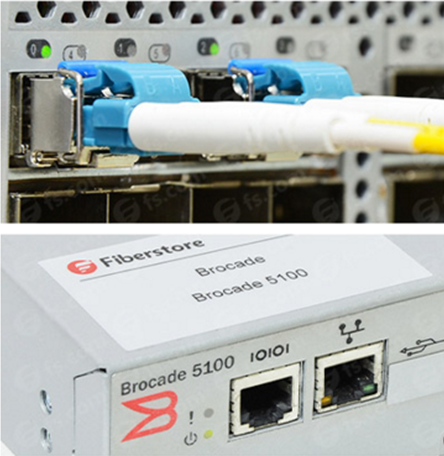
SFP optical transceivers are available in wavelength of 850nm/1310nm/1550nm/1490nm/1530nm/1610nm. Of which the 850nm wavelength is SFP multimode with a limited transmission distance within 2km. While the 1310/1550nm is SFP single-mode, and the transmission distance is longer than 2km. The price of the 850nm/1310nm/1550nm SFP transceiver module is relatively cheaper than the other three. Take E1MG-LX-OM as an example, it is Brocade 1000BASE-LX SFP operating at a wavelength of 1310nm. E1MG-LX-OM can support a link length of 10km. The above image presents a Brocade E1MG-LX-OM with a single-mode fiber inserting into a Brocade Switch.
Features of the SFP Optical Transceiver
- MSA Standard-based Design Assures Compatibility
An SFP transceiver is capable of transferring rates up to 4.25 Gpbs. The MSA standard-based design assures compatibility. XFP form factor is similar to the SFP type. The functionality increases about three times at 10 Gpbs with this type of transceiver type.
- Digital Diagnostics Monitoring (DDM) Enhances Management Capability
Digital optical monitoring (DOM) enables a real time link to be established between the switch and the SFP transceiver. Thus network designers have the ability to monitor real-time parameters such as optical inputs and output power, laser bias, and supply voltage, etc. Additional, the DOM functionality enables the capability to implement digital alarms and warming.
- Hot-swappable Design Facilitates Network Maintenance
SFP transceivers are hot-swappable and have the capability to allow design modification until the final stages of manufacturing. This makes it easier to accommodate different connector interfaces.
Last but not least, an SFP cage may be required for proper operation of the device. It’s usually mounted to the PCB board and will accept the transceiver. It eliminates extra manufacturing steps and reduces costs. SFP transceivers also have a higher optical reliability and will permit higher soldering temperatures. SFP transceivers are recommended by fiber optic component providers to ensure proper data transmission.
Conclusion
SFP transceivers are expected to perform at data speeds of up to 5 Gbps, and possibly higher. Because SFP modules can be easily interchanged, the fiber optic networks can be upgraded and maintained more conveniently than has been the case with traditional soldered-in modules.
Posted by: angelina at
02:15 AM
| No Comments
| Add Comment
Post contains 673 words, total size 6 kb.
May 10, 2016
Evolution is taking placing every minute in the data center in order to better meet people’s needs, and one of the main changes in the data center is that data center designers want to migrate to 40G or 100G without replacing the existing multimode cabling infrastructure. It is known that every data center requires optical transceivers and Direct Attach Cable (DAC) for interconnect. Recently many vendors supply 40G optical devices including QSFP+ optical transceivers, QSFP+ DAC cables and QSFP+ AOC cables. The QSFP+ DAC cables from Cisco and Juniper are highly favored by overall users. Thus in today’s article, we will pay more attention to the illustration of the 40G QSFP+ DAC cables, especially the Juniper QFX-QSFP-DAC-3M and Cisco QSFP-H40G-CU3M.
40G QSFP+ to QSFP+ Direct Attach Copper Cable
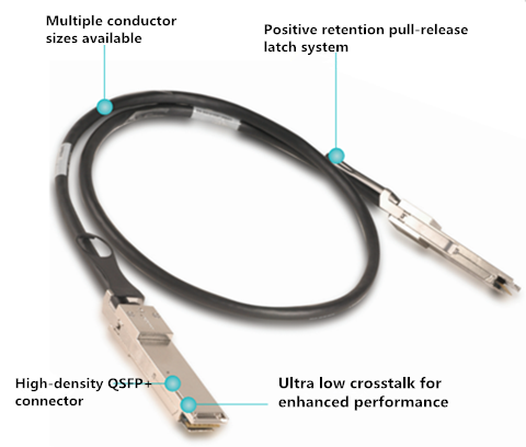
QSFP+ to QSFP+ direct attach copper cable offers a highly cost-effective way to establish a 40G link between QSFP+ ports of QSFP+ switches within racks and across adjacent racks, which is very suitable for very short distances application. These cables connect to a 40G QSFP port of a switch on one end and to another 40G QSFP port of a switch on the other end. Supporting similar applications to SFP+, these four-lane high speed interconnects were designed for high density applications at 10Gb/s transmission speeds per lane. One QSFP+ to QSFP+ direct attach copper cable link is equivalent to 4 SFP+ cable links, providing greater density and reduced system cost. The following image presents an inner structure of QSFP+ DAC cables.
There are two QSFP+ DAC cables available on the market—Passive and active QSFP+ to QSFP+ direct attach copper cables. With an active QSFP+ to QSFP+ direct attach copper cable assembly, the connection is capable of distances of up to 10 meters, while with a passive QSFP+ to QSFP+ DAC cable assembly, the connection is capable of distance of up to 7 m. QSFP+ passive DAC cables are hot-removable and hot-insertable. This cables use integrated duplex serial data links for bidirectional communication and are designed for data rates up to 40 Gbps. Passive DAC cables have no signal amplification built into the cable assembly. The following part will illustrate two passive QSFP+ DAC cables—QFX-QSFP-DAC-3M and QSFP-H40G-CU3M.
- QFX-QSFP-DAC-3M
This Juniper quad small form-factor pluggable plus (QSFP+) DAC cables are suitable for in-rack connections between two QSFP+ ports. It is suitable for short distances of up to 3 m, making itself ideal for highly cost-effective networking connectivity within a rack and between adjacent racks.
- QSFP-H40G-CU3M
This is also a QSFP+ DAC cable just like QFX-QSFP-DAC-3M, but it is from Cisco. As the name implies, it can support a link distance of up to 3 m. Cisco QSFP to QSFP copper direct-attach cables are suitable for very short distances and offer a very cost-effective way to establish a 40GbE link between QSFP ports of Cisco switches within racks and across adjacent racks. To sum up, these two QSFP+ cables have the same performance but used on different Switch brand. Next, a short description about how to use QSFP+ DAC cables will be shown to you.
How to Use a 40G QSFP+ Direct Attach Copper Cable
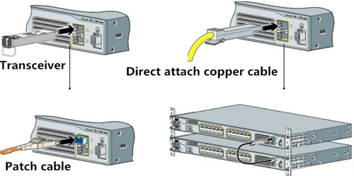
As we known, QSFP+ DAC cables can be mainly divided into two types. One is QSFP+ to 4 SFP+ direct attach breakout copper cable, and the other is QSFP+ to QSFP+ direct attach copper cable. In fact, there is a third type called QSFP+ to 4 XFP breakout cable. However, regardless of what type of cables, they are both used to connect switch to switch or switch to sever. For a QSFP+ to 4 SFP+ direct attach breakout copper cable, it has a QSFP+ connector on one end and four SFP+ connectors on the other end. In terms of a QSFP+ to QSFP+ direct attach copper cable, it has a QSFP+ connector on both ends of the cable. When we use a fiber optic transceiver and patch cable to establish a fiber link, we should firstly plug the transceiver to the switch and then plug the patch cable to the transceiver (see in Figure 2). But for a QSFP+ direct attach copper cable, either SFP+ connector or QSFP+ connector, can be both directly inserted into the switch and don’t need a transceiver at all, which provides a really cost-effective solution for interconnecting high speed 40G switches to existing 10G equipment or 40G switches to 40G switches.
Summary
There are many other vendors offering QSFP+ DAC cables. I can’t list all of them here for you to choose from. Cisco and Juniper QSFP+ DAC cables, as a representative of the QSFP+ DAC cables have been introduced in this article. Just remember that DAC cables must be compatible with the Switches of the network. In fact, the Switch market has been monopolized by large vendors like Cisco, Juniper and HP. And all the original optical transceivers from them are also very expensive. Therefore people are turning to purchase from OEM vendors for the competitive price and high performance. If you are thinking about upgrading to 40G network, QSFP+ DAC cables like QFX-QSFP-DAC-3M and QSFP-H40G-CU3M are indispensable.
Posted by: angelina at
02:25 AM
| No Comments
| Add Comment
Post contains 852 words, total size 6 kb.
May 05, 2016
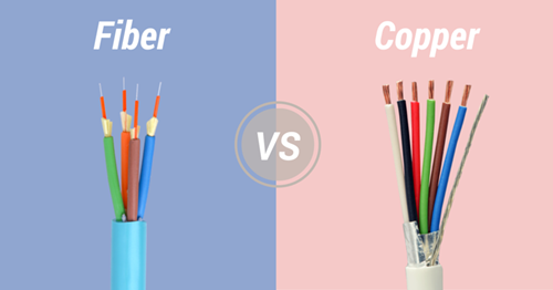
There is no denying that people may encounter a dilemma when accessing which type of network cable (fiber or copper) to install, and which type you should go with. As technology develops further and supporting devices catch up, fiber optic technology is becoming more and more popular. As we know, the most obvious difference between the fiber optic network and copper network is the speed of transmitting data. Associate Professor Robert Malaney has said, "When we are talking about 'speed', we were actually talking about throughput (or capacity)—the amount of data you can transfer per unit time.†Of course, fiber optic cable can definitely transfer more data at higher speed over longer distances than copper cable. So here comes the question: why is the fiber optic technology better than copper?
How Do They Work?
To solve this problem, first we should get down to the working principles of them. Copper network works by sending electrical pulses through a copper wire. The power of the signal dictates how much of it will be retained by the time it reaches its destination. At the destination (e.g. the router), the wire’s electromagnetic field is constantly monitored for changes. As the field gets stronger, the destination registers a "1.†If it dips below a certain measurement, a "0†is registered. Copper cables must have several wires built in to accommodate the mechanisms that allow Ethernet routers to properly process signals. While fiber patch cables transmit data by sending pulses of light generated by a light emitting diode or laser along optical fibers. It conserves the data being sent by not allowing light to stop around the middle, which can be highly beneficial when you’re trying to transfer data over long distances.
Why Fiber Optic Transmission Is Faster?
It is the common sense that fiber can transmit faster data rate than copper. Why is that? Because copper has a significant signal-loss issue. To read a signal correctly during operation, you have to know the exact moment the signal has stopped and the exact moment it began. As a signal is forced to travel farther, the difference between a start and a stop (zero and one) gets very fuzzy. Copper is best used for maintaining a continuous electrical current for the great conductive property. However, for signaling, it remains a very poor material. It’s still good for local networks, but not necessarily something we should be using for global communication infrastructure, considering that Cat6a copper cables can lose 94 percent of their signal at 100 meters distance. Researchers have recently been able to send data at 10 Gbps through copper, but at distances no larger than 30 meters.
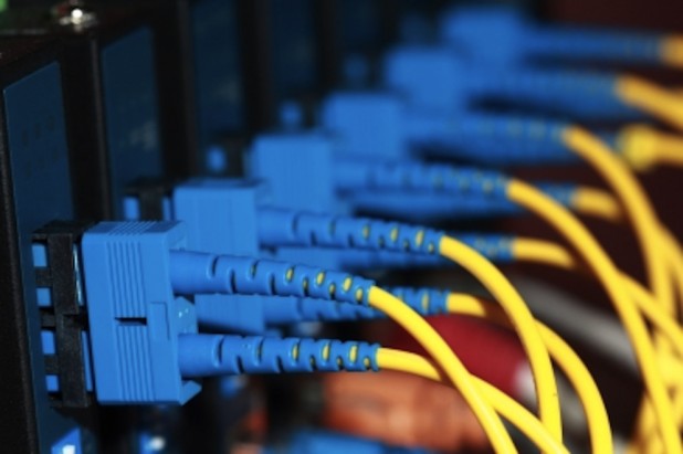
Fiber, on the other hand, can theoretically send terabytes per second of data without so much as a 3% data loss over 100 meters. The signal retention and signal clarity are two things playing an important role here. Not only do you absolutely know when the signal began and ended, but you receive a very strong signal across the wire. This allows communication at dizzying speeds so fast that most routing technologies still can’t process them fast enough. Figure 2 shows a single-mode fiber cable installation.
Through the signal’s lifecycle, fiber does another very important thing: It protects the signal from any electromagnetic interference. EM fields can influence how copper transfers data, but since optical fiber is made of extruded silica, it’s magnetically neutral. If you would have a perfect cable (there’s no such thing yet), you could theoretically send a signal across the United States without making any stops along the way.
Superiority of the Fiber Optic Cable
In both cases you're detecting changes in energy, and that's how you encode data. With copper wires you're looking at changes in the electromagnetic field, the intensity of that field and perhaps the phase of the wave being sent down a wire. With fiber optics, a transmitter converts electronic information into pulses of light—a pulse equates to a one, while no pulse is zero. When the signal reaches the other end, an optical receiver converts the light signal back into electronic information. The following table concludes the reasons why we should choose fiber.
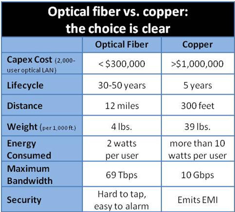
The throughput of the data is determined by the frequency range that a cable will carry. Generally, the higher the frequency range, the greater the bandwidth and the more data that can be put through per unit time. So here we can get the key point: fiber optic cables have much higher bandwidths than copper cables. This difference determines that fiber optic cable can transfer a large sum of data at a very high speed, while the copper cable would attenuate or lose signal strength at higher frequencies. What is more, fiber optic technology is far less susceptible to noise and electromagnetic interference than electricity along a copper cable. For example, when we want to transmit data over 200 kilometers, fiber optic cable can make it perfectly, while the copper cable would suffer a lot of degradation over that distance.
Last but not the least, an added benefit of fiber optic cables is that they are not a fire hazard. This can also be attributed to the same reason that the cables do not produce EMI—there is no electric current traveling through the core. Fiber optic cables do not break as easily, even though the fiber is made of glass, copper wires are more prone to damage than fiber optic cables are.
Summary
Because of its incomparable superiority, fiber patch cable make itself a more enticing cable infrastructure solution than its copper counterpart. It has been utilized in many new cabling installations and upgrades, such as medical examinations, government services, improved productivity, telecommuting, three-dimensional conferencing and working from home. Copper, however, no longer represents a worthwhile investment and should be retired.
Posted by: angelina at
02:17 AM
| No Comments
| Add Comment
Post contains 974 words, total size 7 kb.
32 queries taking 0.0252 seconds, 87 records returned.
Powered by Minx 1.1.6c-pink.

