



June 29, 2016
Optical fiber is the ideal transmission medium for light signals in contrast to copper cable, and it rarely needs amplification. When the signals carried by light travel through the core of fiber jumper cables, the strength of the light will be weaker, as it’s impossible not to incur degradation of light over the length of the network connection. It is inevitable, but if the signal becomes too weak, it will affect the performance of the fiber optic network. So understanding and tackling these losses is a critical part of network installation and testing.
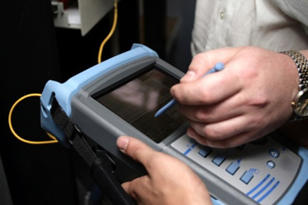
This loss of light power is generally called fiber optic loss or attenuation (measured in dB). High-quality single-mode fiber will often exhibit attenuation. The cause of fiber optic loss located on two aspects: internal reasons and external causes of fiber optic, which we often use the term insertion loss (IL) and return loss (RL) to describe it.
Insertion Loss
Insertion loss refers to the measurement of light that is lost between two fixed points in the fiber, which usually occurs when optical fibers are spliced together, connected, or sent through additional passive network components. It is often attributed to misalignment, contamination, or poorly manufactured connectors (ferrules) and has long been used to advocate fusion splicing. However, in reality, the attenuation difference between fusion splicing and manual connections is marginal (less than 0.1 dB).
Optical connectors might be most likely the cause of high IL, but it’s unfair to think of them as the only culprit. I have watched a splice engineer perform a perfect fusion splice onto a mass-produced, low-cost commodity pigtail, because the Optical Network Terminal (ONT) called for an SC or LC connector. In reality, we can manage connector losses by stipulating the IL standards of the cables we buy, and training installers to keep things clean. Reducing the number of components within the network also logically lowers the insertion loss.
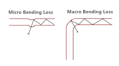
Furthermore, micro and macro-bending (see in Figure 2) may attribute to significant IL, or cracks to the glass caused by over-tensioning (pulling) or by crush and impact damage. This is often the worst kind of attenuation because it takes time to develop and is much more difficult to pinpoint.
Another reason for fiber seemingly exhibiting high IL in fiber to the home (FTTH) networks is the route of the cable itself. For example, a fiber might travel 10km from the OLT to the curb and lose less than 1dB, and then go on to lose three times as much in the next 100 meters. Multi dwelling units (MDUs) are a great example of complex fiber routes, and it is especially important to protect bend radii, such as with dedicated raceways or microducts. Fiber can quite easily become tightly coiled or kinked during installation; even bend insensitive G657A1 fiber coiled just once to 20mm diameter will see as much as 0.2dB loss. Coiled twice at 20mm 0.4dB, three times and... you get the picture.
Return Loss
Fiber Return loss also have great impacts on the network’s performance (see in Figure 3). It refers to the amount of signal reflected back towards the source due to an impedance mismatch effectively, if this is too high, the laser within the network may stop transmitting correctly. Many systems can cope with 40dB return loss (RL), equivalent to 0.01 per cent of the power being sent back. FTTH, however, is more demanding, and RL cannot be more (lower) than -60dB, sometimes higher.
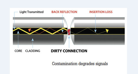
Cable, specifically, can show high RL if a gap exists (such as fiber undercut) or if the fiber is broken. Contamination, torsion, strain or poorly seated connectors can also lead to high return losses. Therefore, it is important that networks are tested to ensure that there aren’t any unexpectedly high RL figures that indicate problems with equipment or fibers. To achieve these ultra-low RL figures, optical connectors must have angled ferrules (APC).
Insertion loss and return loss are not the same thing and, therefore, need to be measured separately. Measuring the RL on the fiber will pinpoint the issue as the response would be unexpectedly high. The complexity of fiber networks, and the need to measure optical losses, can potentially lead to confusion. However, careful planning, use of high-quality components and a focus on testing will enable installers to deliver high-speed connections that perform well over the long term. Here are five easy tips for reducing your losses.
Tips for Reducing Fiber Loss
1. Minimize tight bends that cause light to refract through the fiber cladding. If you need to coil fiber, keep the radius as large as possible.2. Clean connector ferrules little and often - especially before and after testing—and always use the right tools and consumables.3. Decide which is higher: your "power loss" budget or your cable inventory budget. Buying cheap fiber can create larger costs further down the line.4. Avoid any undue stress on the fiber, particularly during installation. Push where possible and if a cable needs pulling, do not exceed the cable’s maximum tensile load.5. Minimize the number of splices or connections in your network; if it means better planning or more innovative drop cables, the investment is probably well worth it.
Conclusion
The power or strength of the signal is typically higher at the head end of the optical network, but lower at the other end because of the fiber loss. To ensure smooth fiber optic transmission, fiber optic loss must be decreased. You can follow the above tips to help you out.
Posted by: angelina at
03:12 AM
| No Comments
| Add Comment
Post contains 919 words, total size 7 kb.
June 24, 2016
The common 40GBASE-LR4 QSFP+ optical transceivers that are available on the market are QSFP-40GE-LR4, QSFP-40G-LR4, QSFP-40G-LR4-S and WSP-Q40GLR4L. They are all compatible with 40GBASE-LR4 standard, but differ with each other. Since I have already explained the difference between the above 4 optical transceivers, I will not go further about these topic today. Except for the different 40GBASE-LR4 QSFP+ transceivers types, there are also two links for 40GBASE-LR4 standards. One is coarse wavelength division multiplexing (CWDM). The other is parallel single-mode fiber (PSM). In this article, these two links of 40GBASE-LR4 QSFP+ transceivers will be introduced to you.
40GBASE-LR4 CWDM QSFP+ Transceiver
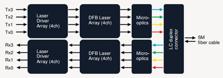
The 40GBASE-LR4 CWDM QSFP+ transceiver (likeQSFP-40GE-LR4) is compliant to IEEE P802.3ba 40GBASE-LR4 standard. This QSFP module supports link lengths of up to 10km over single-mode fiber (SMF) with duplex LC connectors. This transceiver converts 4 inputs channels of 10G electrical data to 4 CWDM optical signals by a driven 4-wavelength distributed feedback (DFB) laser array, and then multiplexes them into a single channel for 40G optical transmission, propagating out of the transmitter module from the SMF. Reversely, the receiver module accepts the 40G CWDM optical signals input, and demultiplexes it into 4 individual 10G channels with different wavelengths. The central wavelengths of the 4 CWDM channels are 1271, 1291, 1311 and 1331 nm (defined as members of the CWDM wavelength grid in ITU-T G694.2). Each wavelength channel is collected by a discrete photo diode and output as electric data after being amplified by a transimpedance amplifier (TIA).
40GBASE-LR4 PSM QSFP+ Transceiver
Unlike CWDMQSFP+ transceiverusing a LC connector, PSM QSFP+ is a parallel single-mode optical transceiver with an MTP/MPO fiber ribbon connector. It also offers 4 independent transmit and receive channels, each capable of 10G operation for an aggregate data rate of 40G on 10km of single-mode fiber. Proper alignment is ensured by the guide pins inside the receptacle. The cable usually cannot be twisted for proper channel to channel alignment. In terms of a PSM QSFP+, the transmitter module accepts electrical input signals compatible with common mode logic (CML) levels. All input data signals are differential and internally terminated. The receiver module converts parallel optical input signals via a photo detector array into parallel electrical output signals. The receiver module outputs electrical signals are also voltage compatible with CML levels. All data signals are differential and support a data rates up to 10.3G per channel.
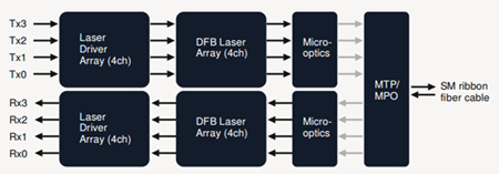
Compare 40GBASE-LR4 CWDM QSFP+ With 40GBASE-LR4 PSM QSFP+ Transceiver
As noted before, 40GBASE-LR4 CWDM QSFP+ transceivers use a duplex LC connector via 2 optical single-mode fibers to achieve 40G without making any changes to the previous 10G fiber cable plant. However, 40GBASE-LR4 PSM QSFP+ transceivers use an MTP/MPO fiber ribbon connector via 8 optical single-mode fibers to reach 40G. Obviously, CWDM QSFP+ is a more cost-effective solution for 40G connectivity.
What’s more, in terms of the inner structure of an optical transceiver module, PSM QSFP+ uses a single uncooled CW laser that splits its output power into four integrated silicon modulators, which is much inexpensive than CWDM QSFP+. Besides, its array-fiber coupling to an MTP connector is relatively simple. A picture comparing the key differences between CWDM and PSM is shown below:

Additionally, the caveat is that the entire optical fiber infrastructure within a data center, including patch panels, has to be changed to accommodate MTP connectors and ribbon cables, which are more expensive than conventional LC connectors and regular SMF cables. Not to mention that cleaning MTP connectors is not a straightforward task.
Conclusion
PSM and CWDM are the two links of 40GBASE-LR4 QSFP+ transceivers. Both of them can support a link distance of 10km. However, 40GBASE-LR4 CWDM QSFP+ are more common than 40GBASE-LR4 PSM QSFP+ because of its performance and low cost. Fiberstore offers a wide brand compatible 40G CWDM QSFP+ transceivers. Each of our fiber optic transceivers has been tested to ensure its compatibility and interoperability.
Posted by: angelina at
02:22 AM
| No Comments
| Add Comment
Post contains 655 words, total size 6 kb.
June 15, 2016
In such a digital world, human beings are keen on developing technologies to facilitate daily lives. In order to process and store tons of information, many different forms of storage like CD-ROM, USB Key, and DVD has been developed. However, the above devices can only store limited data, which is not adequate for the information explosion. Thus cloud computing, as an advanced storage solution, appears on the stage. So how to achieve cloud computer? Different voices with different opinions emerge, but from a technician’s standpoint, a reliable cabling connectivity or fiber jumper is key to cloud computing. Whether you agree with my opinion or not, the following article will provide some detailed information about it to help you find out the answer.
What Is Cloud Computing?
The "Cloud†in the term cloud computing, describes an image of the complex infrastructure, covering all the technical details. Obviously, the cloud computing has nothing to do with the weather "cloudâ€. It is just an analogy to give it a body to imagine. Cloud computing is a model for computing transforming. In this model, data and computation are operated somewhere in a "cloudâ€, which is some collection of data centers owned and maintained by a third party. This enables ubiquitous, convenient, on-demand network access to a shared pool of configurable computing resources that can be rapidly provisioned and released with minimal management effort or service provider interaction.
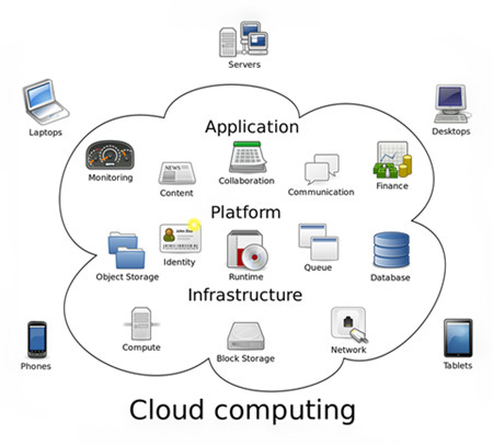
There are public cloud, private public and hybrid cloud. When a cloud is made available in a pay-as-you-go manner to the general public, we call it a public cloud. And when the cloud infrastructure is operated solely for a business or an organization, it is called private cloud. A composition of public and private cloud is called hybrid cloud. A hybrid cloud integrates the advantages of public cloud and private cloud, where private cloud is able to maintain high service availability by scaling up their system with externally provisioned resources from a public cloud when there are rapid workload fluctuations or hardware failures.
Optical Fiber Is the Key to Cloud Computing
In the "cloud†network, subscribers’ terminals are simplified into a pure and single device with only input and output functions but meanwhile utilize the powerful computing and processing functions from the "cloudâ€. This means that the terminal must have a very fast connection, because the simple terminal means fast network and powerful platform requirement, where "pipes†are put forward higher requirement. Thus, fiber is the ideal "pipe†for cloud computing. The following image shows the evolution of memory storage.

In fact, computer applications, software and even file storage now reside on the Internet or in the "cloudâ€. Yet another driving force is mobile Internet traffic, which relies heavily on cloud computing. It is said that there is over 1 Exabyte of data currently stored in the cloud. And this number is growing exponentially every day. The greatest thing that will limit your ability to work seamlessly in the "cloud†is your Internet connection. Thus, to access the tremendous amounts data, we need fiber networks that can carry Terabits—one trillion bits per second. Fiber jumper cables can offer more available bandwidth and speed which meets the demands of the "cloudâ€. Obviously, no technology is more effective at meeting that challenge than fiber at present.
What’s more, FTTH infrastructure is expected as a solution to meet the growing demands for high bandwidth. It brings fiber optic connections directly into homes, allowing for delivery speeds up to a possible 100 Mbps, or even more. These speeds open the door to a variety of new services and applications for residential, business and public service markets. The relationship between FTTH and cloud computing is subtle. FTTH encourages the growth of cloud computing with its benefits. And cloud computing may in turn drives the development of FTTH.
Conclusion
As cloud computing market continues to mature, current and potential information technology capabilities offers many benefits to our lives. However, just like other new technology advancement, cloud computing also faces many challenges, which requires all of us to form thoughts on the strengths and downfalls of the technology. Fiber optic cable, as an indispensable component of network infrastructure, plays a vital role in cloud computing.
Posted by: angelina at
02:34 AM
| No Comments
| Add Comment
Post contains 709 words, total size 6 kb.
June 07, 2016
FTTH (Fiber to the Home) network compared with technologies now used in most places, increases the connection speeds available for residences, apartment building and enterprises. FTTH network is the installation and use of optical fiber from a central point known as an access node to individual buildings. The links between subscriber and access node are achieved by fiber jumper cables. Loose-tube and tight buffer cables are commonly used to transmit signals with high speed, which are capable of supporting outdoor or indoor environment. Is there a cost-effective solution that can support both indoor and outdoor environment in FTTH network? To answer this, the construction and comparison of loose tube cable and tight buffer cable will be introduced in the following article.
Loose-Tube and Tight-Buffer Cable
The "buffer†in tight buffer cable refers to a basic component of fiber optic cable, which is the first layer used to define the type of cable construction. Typically a fiber optic cable consists of the optical fiber, buffer, strength members and an outer protective jacket (as showed in Figure 1). Loose-tube and tight-buffer cables are two basic cable design. Loose-tube cable is used in the majority of outside-plant installations, and tight-buffered cable, primarily used inside buildings.
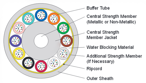
Loose-tube cable consists of a buffer layer that has an inner diameter much larger than the diameter of the fiber see in the following picture. Thus, the cable will be subject to temperature extremes in the identification and administration of fibers in the system. That’s why loose-tube cables are usually used in outdoor application. The loose-tube cables designed for FTTH outdoor application are usually loose-tube gel-filled cables (LTGF cable). This type of cable is filled with a gel that displaces or blocks water and prevents it from penetrating or getting into the cable.
Tight buffer cable using a buffer attached to the fiber coating is generally smaller in diameter than loose buffer cable (showed in Figure 2). The minimum bend radius of a tight buffer cable is typically smaller than a comparable loose buffer cable. Thus tight buffer cable is usually used in indoor application.
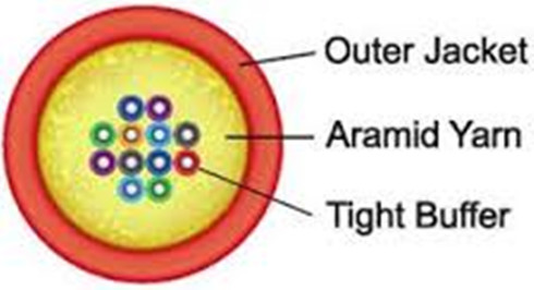
Tight buffered indoor/outdoor cable with properly designed and manufactured can meet both indoor and outdoor application requirements. It combines the design requirements of traditional indoor cable and adds moisture protection and sunlight-resistant function to meet the standards for outdoor use. Tight buffered indoor/outdoor cable also meets one or more of the code requirements for flame-spread resistance and smoke generation.
Choose Tight Buffer Cable for FTTH Network
The inner construction of tight buffer indoor/outdoor cable have been introduced above. The following will explain why tight buffered indoor/outdoor cable is a better FTTH cabling solution. Figure 3 shows a clear structure of FTTH network.
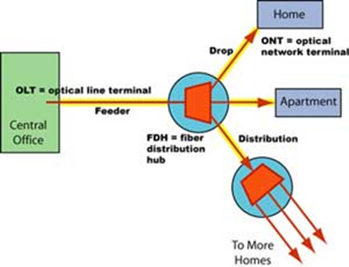
Using the traditional choice of LTGF cables as the outdoor cable, there would be a conversion from one fiber type to another type, which includes prep work on the fiber, the need for splice tray, the routing of fibers in the tray, and other similar detail. Before termination and splicing, the gel of LTGF cable must be cleaned and the breakout point of the main cable must be blocked by some method to prevent oozing of the cable gel. In addition, this cable type must normally be terminated or spliced close to the cable entryway of a building to switch to indoor cable, as it generally incompatible with indoor fiber codes. This time consuming and labor intensive process adds hidden costs to install the LTGF cables.
However, using only tight buffer indoor/outdoor cable for FTTH is much more convenient and cost-effective. A tight-buffered indoor/outdoor cable can be used throughout the link, requiring no transitions at the building entryway. Tight buffer indoor/outdoor cable requires less care to avoid damaging fibers when stripping back the cable. The termination and splicing of these cables are easier than that of LTGF cables.
An important reason why choose tight-buffered indoor/outdoor cable for FTTH cable installation is the reliability of the overall system. Splicing are the weakest point in a FTTH network. With splicing, the bare fiber ends are open to dust, dirt, water, vapor, and handing which might reduce the fiber strength and increase brittleness. Choosing loose tube outdoor cable for FTTH, there will be splices after the conversion from one cable type to another type. The splices inside a building may be held in a cabinet that is open to the air, which might decrease the reliability of the FTTH network. Using the tight buffer indoor/outdoor cable could eliminate splicing and improve the installation reliability greatly.
Conclusion
This article has explained loose-tube and tight buffer indoor/outdoor cables. Network installer can run a single cable type and remove a transition point between the outside plant and the inside plant. At the same time, the reliability of the overall FTTH network can be increased greatly.
Posted by: angelina at
02:31 AM
| No Comments
| Add Comment
Post contains 807 words, total size 7 kb.
June 03, 2016
A smooth connection between cable and other optical devices allows the optical signals to pass with low attenuation and little return loss, which is vital for telecommunication network. Fiber optic pigtails, compared with the regular fiber jumper, is terminated with fiber optic connector at only one side of the cable, which are usually used with fiber optic management equipment like ODF, splice closures and cross cabinets. Today’s article will provide some detailed information about fiber optic pigtails.
What Is Fiber Optic Pigtail?
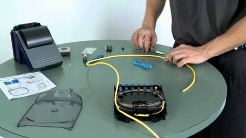
Fiber optic pigtail is also called bare fiber. It is a kind of optical cable terminated with fiber optic connectors at one side of the cable while leave the other side no connectors, so that the connector side can link to the equipment (eg. fiber converter or optical transceiver module) and the other side can be melted with optical fiber. In fact, fiber optic pigtail and patch cord are similar in structure, fiber optic patch cable is composed of a fiber optic cable terminated with connectors on both ends. Sometimes, we cut the fiber optic patch cord in the middle, strip its jacket and then end up with a pigtail. Figure 1 shows the process of fiber optic pigtail splicing.
Fiber optic pigtails are designed to meet or exceed all of the performance requirements for current and proposed applications. They are available in various optical connector type, single-mode and multimode fiber, as well as fiber counts and cable structure. Here is what you need to know about the classification of fiber optic pigtails.
Divided by the Optical Connectors
Commonly used fiber optic pigtails are available in SC, FC, LC, ST, MU, E2000 and MTRJ type.
LC Fiber Optic Pigtails: LC features the low cost and high precision 1.25mm outer diameter ceramic ferrules and highly favored for single mode applications. LC fiber optic pigtail use LC connector and suit for density installations.
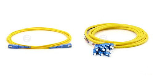
SC Fiber Optic Pigtails: SC connector is a non-optical disconnect connector with a 2.5mm pre-radiused zirconia or stainless alloy ferrule. It is light weight and economic to use in different applications such as CATV, LAN, WAN, test and measurement. SC fiber optic pigtails are also a commonly used pigtail type in cable installation. The following picture shows a SC fiber cable (left) and SC fiber optic pigtail (right) .
ST Fiber Optic Pigtails: ST fiber optic connector is the most popular connector for multimode fiber optic LAN applications. It has a long 2.5mm diameter ferrule made of ceramic (zirconia), stainless alloy or plastic. SC fiber optic pigtails are used in telecommunications, industry, medical and sensor fields.
FC Fiber Optic Pigtails: FC fiber optic pigtails use the metallic body FC fiber optic connectors. FC features the screw type structure and high precision ceramic ferrules. FC fiber optic pigtails and related products are known for the general and average applications.
MU Fiber Optic Pigtails: MU connector is called "mini SC†as it is only half size of the SC and are more popular in Japan. Applications of MU connectors include high-speed data communications, voice networks, telecommunications, and dense wavelength division multiplexing (DWDM). MU fiber optic pigtails use the MU connector that inherits the features and advantages of SC connector.
MT-RJ Fiber Optic Pigtails: MT-RJ fiber optic pigtails use the MT-RJ connectors that are specially designed for fast Ethernet. They are all duplex types with a mini ribbon fiber inside. MT-RJ inherit the features from the MT connectors and RJ45 connectors, as its name "MT-RJâ€. MT-RJ optical fiber pigtails are small form connector products that fit for density applications.
E2000 Fiber Optic Pigtails: E2000 connector features a spring-loaded shutter which fully protects the ferrule from dust and scratches. With 1.25mm ferrule, snap-in mechanism, it is available in single mode and multimode. E2000 fiber optic pigtails also have a wide range of applications.
Single-mode and Multimode Fiber Optic Pigtails
Just as fiber optic patch cords, fiber optic pigtails can also be designed in multimode and single-mode fiber. Multimode fiber optic pigtails use 62.5/125 micron or 50/125 micron bulk multimode fiber cable and terminated with multimode fiber optic connector at one end. General multimode fiber optic cable jacket color is usually orange. In addition, 10G multimode fiber cables (OM3 or OM4) are also available in fiber optic pigtails. The jacket color of 10G OM3 and OM4 fiber optic pigtail is usually aqua.
Conclusion
Fiber optic pigtail can be fusion spliced onto a pre-terminated fiber optic cable assembly to extend the cable distance or onto field-terminated cables to provide the connectorized end. As noted before, fiber optic pigtail can be categorized by different standard. According to the cable jacket materials, there are PVC/LSZH fiber optic pigtail, armored fiber optic pigtail and waterproof fiber optic pigtail, etc.
Posted by: angelina at
04:26 AM
| No Comments
| Add Comment
Post contains 788 words, total size 6 kb.
32 queries taking 0.1791 seconds, 85 records returned.
Powered by Minx 1.1.6c-pink.

