



January 31, 2016
Ethernet and Fibre Channel are the two typical networks that data center will utilize to present operational and maintenance issues. Traditional Ethernet is a family of frame-based computer networking technologies for local area networks (LANs), whereas Fibre Channel is used for storage area networking (SANs). Fiber over Ethernet (FCoE) is a storage networking protocol that supports Fibre Channel over Ethernet. This article will provide an overview of FCoE, describe the importance to data center that make up the new ecosystem, and explains how the technology is developed today.
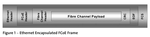
FCoE combined with the advent of 10 Gigabit Ethernet (10 GE) fabrics will grant companies the ability to consolidate their I/O, cables, and adapters while at the same time increase the utilization of their servers. Conceptually FCoE can be broken down into three components: encapsulation of a Native Fibre Channel Frame into an Ethernet frame , the extension of Ethernet to become a lossless fabric, the replacing of a Fibre Channel link with MAC addresses in a lossless Ethernet fabric.
I/O consolidation means a customer can use multi-function network/storage adapters in place of single-function network-specific and storage-specific cards, thereby reducing the number of server slots and switch ports, as well as reducing the number of power consumed for I/O and necessary cooling. This also results in fewer points of management administrators will have to control. A reduction in NICs through I/O consolidation has an additional important advantage. The ability to cool a set amount of heat generated per rack is the primary barrier to data-center expansion and inefficiency encountered today. Reducing the amount of NICs in servers can reduce the amount of heat those servers generate.
Posted by: angelina at
08:48 AM
| No Comments
| Add Comment
Post contains 635 words, total size 6 kb.
January 30, 2016

Telecom infrastructure company Zayo Group Holdings will make an investment of $14 million to provide fiber-to-the-tower (FTT) to 78 new towers in Indiana to serve a wireless customer.
Zayo said the towers will be located on 234 new network miles south and west of Indianapolis and connect a corridor to Louisville, Kentucky. The sale will also leverage 350 miles of fiber that is already in place to create a diverse ring in the region.
Zayo expects this contract to result in a strong return on the incremental $14 million capital investment to construct the additional 234 route miles of fiber network. Zayo expects to use the network to serve additional wireless tenants. Zayo will also provide fiber-based services to non-wireless customers such as universities, school districts, hospitals and content providers.
There are financial service, insurance, technology and healthcare businesses, in addition to several state and private universities in Indianapolis and the surrounding area.
"Our network will have the capacity to not only provide FTT infrastructure for one of the nation’s leading wireless carriers, but also the fiber capacity to support services to additional mobile operators and other customers in need of high-bandwidth solutions,†said Jacob Fuller, vice president of Zayo’s Mobile Infrastructure segment.
After this expansion, Zayo will have approximately 8,200 towers, including those under construction and those already connected to its fiber network.
Posted by: angelina at
02:16 AM
| No Comments
| Add Comment
Post contains 237 words, total size 2 kb.
January 28, 2016
With the speed in the data center now increases from 10G to 40G, different optical technology and cabling are required. But at first we should figure out the design of 40G Ethernet network. There are several key factors that may affect the transition to 40G. This article today will pay special attention to those aspects that influence data center design consideration.
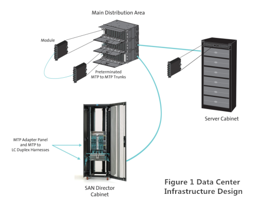
The MPO is defined by TIA-604-5-C, Fiber Optic Connector Intermateability Standard. Type MPO (FOCIS-5) as an array connector that can support up to 72 optical fiber connections in a single connection and ferrule. While the MPO is versatile in the fiber count supported, the 12-fiber MPO is the version widely deployed. Many data center designs today use cassette-based duplex LC connectivity or MPO to duplex LC harnesses at the electronics interface, while 12-fiber MPO-based connectivity is used to connect the trunk cabling to each cassette or harness.
-
40GBASE-SR4 (parallel optics)
100m on OM3/125m on OM4—10G on four fibers per direction
- 40GBASE-LR4(cWDM)
10km on single-mode fiber—4x10G 1300nm wavelength region
- 40GBASE-CR4
7m over copper—4x10G (twinax copper)
- 40GBASE-FR(Serial)
2km on single-mode—4x10G 1550nm
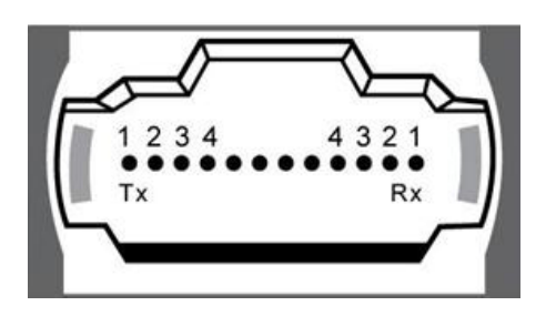
As noted above, the QSFP+ module is specified for use with different standard. The 40GBASE-SR4 is terminated with the MPO connector. For example, CiscoQSFP-40G-SR4QSFP+ transceiver enables high-bandwidth 40G optical links over 12-fiber parallel fiber terminated with MPO/MTP multifiber female connectors.
For 12-fiber MPO cassette-based optical systems already installed, 40G migration is as simple as removing the existing cassette from the patch panel housings at the equipment and cross connects and replacing the cassette with an MPO adapter panel. Next, an appropriate 12-fiber MPO jumper would be used to cross-connect the trunk cabling as well as interconnect into the QSFP. Though not widely available currently, future preterminated system trunks may utilize 24-fiber MPO connections, both on the trunks and on the cassette. In this case, 40G deployment would require an interconnect harness terminated with two 12-fiber MPO connectors at the QSFP end, and one 24-fiber MPO at the trunk end. This would provide the needed interface with the 24-fiber MPO-based trunk and the 40G QSFP. A 24-fiber MPO jumper would be needed at the system cross connects to ensure polarity was maintained and that skew was within requirements.
Posted by: angelina at
02:43 AM
| No Comments
| Add Comment
Post contains 675 words, total size 7 kb.
January 26, 2016
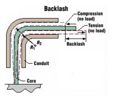
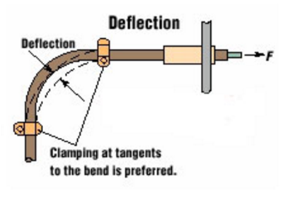
Push and pull usually come as the opposite side, but in the case of telecommunication field, they definitely come hand in hand. Push-Pull or Pull-Pull cables are used for greater freedom in routing allowing for smaller bend radii in some installations. Their typical applications include vent air controls and mechanical starters in aircraft. This article today will address these two cables in detail.
While Pull-Pull cables in most cases are more flexible and are used in the tension (Pull) mode. The design has an integral return spring maintaining the load on the cable returning it to the standby position. This spring allows the use of flexible cables allowing tighter radius. Maximum working loads should be minimum breaking load of the core plus a built in safety factor.
Posted by: angelina at
03:19 AM
| No Comments
| Add Comment
Post contains 666 words, total size 7 kb.
January 22, 2016
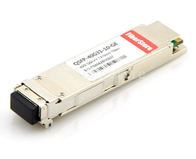
In 2010, the IEEE ratified the 802.3ba standard for 40/100GbE. Similar to how transportation highways are scaled to support increased traffic with multiple lanes, the 40GbE standards use parallel optics, or multiple lanes of fiber transmitting at the same speed. This cost effective 40GbE solutions are a key enabler for delivering support for higher bandwidth flows, lower latency and deterministic load sharing, whichpromote40G QSFP+ taking off in 2013. 40G QSFP+ modules have gained much popularity among users. This article will provide some detailed information about QSFP+ modules, especially Juniper QSFP options.
- The Juniper JNP-QSFP-40G-LX4 module for SMF/MMF links in 2km/150m, respectively.
- The Juniper QFX-QSFP-40G-SR4 module for MMF links for a distance of 150m.
- The Juniper JNP-QSFP-40G-LR4 modules for SMF for a distance of 10km.
- The Juniper 40G QSFP+ to 4 10G SFP+ direct-attach copper breakout cables in lengths of 1 and 3m.
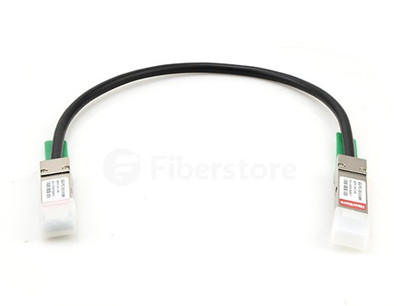
- The Juniper QSFP+ to QSFP+ direct attach copper cables enable a very short length of 1, 3 and 5m.
Main Features of Juniper 40G QSFP+ Modules
- Support for 40GBASE Ethernet
- Hot-swappable input/output device that plugs into a 40-Gigabit Ethernet QSFP+ Juniper switch port
- Flexibility of interface choice
- Interoperable with other IEEE-compliant 40GBASE interfaces available in various form factors
- Support for "pay-as-you-populate" model
- Support for the Cisco quality identification (ID) feature which enables a Juniper switch to identify whether the module is certified and tested.
Posted by: angelina at
02:29 AM
| No Comments
| Add Comment
Post contains 602 words, total size 7 kb.
January 20, 2016

Chinese networking vendor ZTE maintained its strong profit growth in 2015, but this time it was fuelled by a healthy jump in revenues as much as cutting overheads.
In its guidance for full-year 2015 ZTE said it expects revenue to top RMB 100 billion, with improved sales of LTE and optical networks driving the growth as well as smart city, enterprise ICT solutions and routers.
This will mark a 24% increase in revenues from 2014, which saw ZTE almost double its profits in spite of modest revenue growth thanks to a fairly extensive streamlining exercise. 2015 profits didn’t increase by such a large ratio this time but by a similar number in absolute terms – jumping by 44% to RMB 3.78 billion.
ZTE recorded higher sales of 4G long-term evolution (LTE) network solutions internationally, in addition to China,†said the ZTE announcement. "The company also posted increased sales of optical network solutions as the demand for broadband networks strengthens.
The growth in annual revenue was also driven by increased sales of high-end routers in overseas markets, while ZTE posted higher revenue from sales of enterprise information and communications technology (ICT) solutions including smart city and data centre solutions to companies and government departments. In addition, ZTE also boosted sales of 4G smartphones outside China, as well as terminal products for homes.
Posted by: angelina at
09:57 AM
| No Comments
| Add Comment
Post contains 231 words, total size 2 kb.
January 19, 2016
From 3Mbps to the IEEE 802.3ba standard now supporting 40/100G speed, telecommunication field has gone through a huge migration. Let us ignore what has happened in this process, and take a look at the sudden emergence of 40G network, which has far-reaching significance to the user. From the equipment point of view, high-density 40GbE core switch board is the general trend, especially in the field of data center switches. 40G products have currently been mass produced. Many major vendors like Cisco, HP, Juniper and Mellanox have released a large variety of 40G devices including 40G transceiver and 40G cables. Of whichMellanox QSFP+will be introduced in this article in detail.
- Mellanox QSFP SR4 module uses MTP/MPO connector type to connect an OM3/OM4 fiber cable.
- Mellanox QSFP SR4E module uses MPO connector type to connect OM3 and OM4 fiber cables.
- Mellanox QSFP LR4 module uses LC-LC connector type to connect a fiber cable.
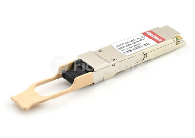
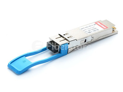
QSFP+ transceivers are designed to carry Serial Attached SCSI, 40G Ethernet, QDR (40G) and FDR (56G) Infiniband, and other communications standards. QSFP modules increase the port-density by 3x-4x compared to SFP+ modules. Mellanox’s QSFP+ optical transceiver is designed to provide outstanding performance in high bandwidth applications such as FDR InfiniBand and Ethernet, at speeds up to 56Gb/s and reaches up to 30 meters. Each of Mellanox’s 56Gb/s QSFP modules contain four fiber optic transceivers, each operating at data rates of up to 14.0625Gb/s. Rigorous production testing ensures the best out-of-the-box installation experience, performance and durability.
Posted by: angelina at
03:19 AM
| No Comments
| Add Comment
Post contains 531 words, total size 6 kb.
January 15, 2016
Optical fiber cabling had gone through rapid development over recent years and maintained its leading role in telecom field. While twinax cable still remained a good way to access the networking industry trends over the last three decades and presented the highest longevity among all media. Twinax cable (see in following Figure) is a type of cable similar to coaxial cable that has two inner conductors instead of one. And owing to its cost efficiency, it is commonly used in short-range high-speed differential signaling applications. Currently there is a twinax cable which comes in either passive or active copper cable. So what is the difference between them? Today’s passage will provide a satisfying solution to you.
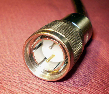
When the distance between connection points exceeds 5m, it is highly recommended to use active cables to ensure signal is transferred all the way through. The downside is that they are more expensive and use more power. The upside is that you don't have to worry about distance (up to 300 meters) and, perhaps more importantly, you don't have to worry about which vendor’s cable you use and the signal is improved and gives peace of mind by creating a trustworthy connection. In regards to active versus passive twinax cables, it depends on what you are connecting together.
QSFP to 4SFP+ copper breakout cables are suitable for very short distances and offer a very cost-effective way to connect within racks and across adjacent racks. TakeQSFP-4SFP10G-CU1Mas an example, this breakout cable connects a 40G QSFP port and four 10G SFP+ ports of Cisco switches and operates at a link length of 1m. While a QSFP+ to QSFP+ passive copper cable consists of a cable assembly that connects directly into two QSFP+ modules, one at each end of the cable. This cable use integrated duplex serial data links for bidirectional communication and is designed for data rates up to 40Gbps. There are various QSFP+ to QSFP+ passive copper cables branded by famous brands, like Cisco, HP, Juniper, Brocade, etc. The following picture shows a CiscoQSFP-H40G-CU3MCompatible QSFP+ to QSFP+ passive copper cable.

Posted by: angelina at
03:28 AM
| No Comments
| Add Comment
Post contains 662 words, total size 6 kb.
January 13, 2016
A heated debate over whether fiber will take place of copper in the near future has caught people’s attention lately. Five to seven years ago, fiber was considerably more expensive than copper and, as such, was used sparingly. As fiber price has dropped dramatically and our bandwidth needs have grown, data centers have started to use more fibers all the way to their infrastructure. Under this circumstance, people wonder that copper cabling may soon be out of the stage of telecom industry. But the truth is that there is a still a place for copper cabling in the data center, even in 40G data center.
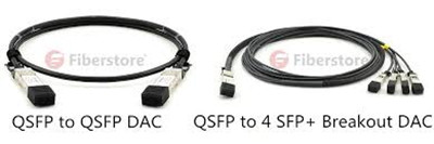
The problem of standard twinaxial cables is not their performance as much as their tendency to be stiff and bulky, thus consuming precious rack space and blocking critical airflow. The current copper solution for 40G Ethernet limits the architectures one can deploy. 40G Ethernet QSFP+ DAC cable assemblies have a reach of 5 to 7 meters. Thus QSFP+ DAC cable (or QSFP+ breakout cable) assemblies cannot be used for most end-of-row (EoR) implementations or other architectures. What’s worse, DAC cable assemblies are a point-to-point solution and therefore cannot support a structured cabling design. Designers must be careful not to bend the cables too much because the cable’s shielding and overwrap materials can distort the precise cable geometry needed to maintain impedance control, which can degrade signal performance. Moreover, the wrapped shield, with repeated breaks in the shield along the cable length, can produce an unwanted resonance effect, evident at certain frequencies.
Posted by: angelina at
03:00 AM
| No Comments
| Add Comment
Post contains 767 words, total size 6 kb.
January 11, 2016
SAN FRANCISCO – Ford is making a big push to get intimately involved with the daily mobility needs of all motorists, regardless of whether they own a Ford automobile.
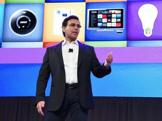
In April, the automaker will launch a smartphone app called FordPass that helps users with parking and other services, provides live assistants via chat or voice, and offers reward-based programs with partner companies. Although FordPass can be used by anyone, it offers the most benefits to Ford vehicle owners.
Ford also will roll out four new FordHubs that, much like interactive kiosks at events such as the North American International Motor Show, opening Monday in Detroit, are designed to showcase the company’s various Ford Smart Mobility initiatives. They won't be points of sale.
"We don’t just want to be in the vehicle business, we want to be in the connected relationship business,†Ford CEO Mark Fields told USA TODAY. "Anyone can make an app. This is more than that. It’s about a platform that has a digital as well as physical presence in the lives of anyone who uses transportation.â€
FordPass is a bold and logical step from Fields. Since taking the reins in 2014, he's been maneuvering his company to to source new revenue streams in a transportation future powered by Millennials who typically see more value in car sharing than ownership. Fields has been particularly aggressive in pushing forward into autonomous cars — fleets of which may form the next great urban transportation network — and driver-assist systems, both of which he discussed at last week's auto-tech-filled 2016 Consumer Electronics Show in Las Vegas.
Ford executives say that the 18-month project leveraged deep dives into a range of digital branding successes including Amazon’s Mayday button (which summons a live consultant to a Kindle Fire screen), Burberry’s in-store digital runaway experiences (bringing apparel to life for shoppers) and Nespresso’s customer-centric strategy (which includes a mix of retail outlets and phone consultants).
When FordPass launches, users can book and pay for off-street parking in advance.Partner companies will include ParkWhiz and Parkopedia. Using the app,another partner, FlightCar, offers the opportunity to rent out your vehicle for paywhile you’re away on a trip.FordPass will be available first in the U.S. and Canada, followed by specific European markets as well as China and Brazil.
Tapping into even the smallest percentage of mobility-related transactions of commuters would result in significant sales. Similarly, FordPass app fans who might be in the market for a vehicle could translate to new customers.
Fields says FordPass may well be used by people "who may never buy a Ford, but we still want to be part of making their lives easier.â€
Also part of the FordPass roll out is a user loyalty program with two initial partners, McDonald’s and 7-Eleven. While details are still coming into focus, the idea is that FordPass users who shop at those businesses can accrue points while in turn the retailers can offer shopping incentives to users through the app. At launch, the partnership roster seems thin. But Fields says the company is carefully evaluating who to sync up to FordPass. . "There has to be a meeting of minds," he said.
Not surprisingly, the full suite of FordPass options are available only toFord car owners, specifically thosewith vehicles equipped with Sync Connect infotainment systems. TheFordPass appwillprovideaccess to features such as remote start, lock and unlock, vehicle location assistance,updates on fluid levels, and the opportunity toschedule dealership appointments.
Posted by: angelina at
09:19 AM
| No Comments
| Add Comment
Post contains 581 words, total size 5 kb.
January 08, 2016
When you look at the evolution of networking and the data that drives it, there is no surprise that Ethernet has been and will continue to be the most widely used network interface. Consumers and network designers wish to smoothly migrate to higher network speed—100G/400G without compromising quality. Ethernet speed upgrade path was clearly defined as from 10G,40G to 100G. But recently a new migrate path (10G-25G-100G) was gradually accepted by subscribers. For those who need to migrate their network to adopt to the big data age, choose 25G or 40G Ethernet, that is the question! This article provides the pros and cons of 25G and 40G Ethernet network. You will get your own answer at the end of it.
Here Comes 25 Gigabit Ethernet
25 Gigabit Ethernet has passed the first hurdle in the IEEE standards body with a successful Call for Interest (CFI) in July, 2014. It is a proposed standard for Ethernet connectivity that will benefit cloud and enterprise data center environments. 25 GbE leverages technology defined for 100 Gigabit Ethernet implemented as four 25 Gbit/s lanes (IEEE 802.3bj) running on four fibers or copper pairs. Telecom giants like Google, Microsoft, Arista, and Mellanox are pushing the development of a 25 Gigabit Ethernet standard for top-of-tack server networking. Relevant transceiver modules and optical cables are developed to support this technology.
40G Ethernet Network
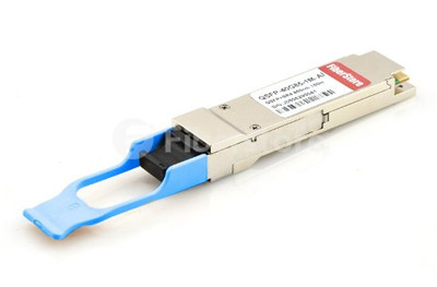
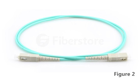
The IEEE P802.3ba 40G and 100G Ethernet Task Force was formed to develop a 40 Gigabit Ethernet and 100 Gigabit Ethernet draft standard. At the physical layer, 40G Ethernet is essentially 4×10G lanes. Standards-based 40G Ethernet switches and routers are starting to show up in enterprise networks, following ratification of the IEEE 802.3ba specification in mid-2010. QSFP+ modules and 40G DAC cables are introduced to back 40G networking, which are warmly welcomed by network designers. For example, QSFPP-4X10GE-LR (see in Figure 2) is compatible Juniper QSFP+ transceiver. It can be used in a 4×10G modules with 10GBASE-LR interfaces.
25 Gigabit or 40 Gigabit Ethernet for Your Server
The most obvious feature of 25 Gigabit is described in two words—single lane. The phrase refers to the electrical signaling on the chip that would power an Ethernet port, while the design of 40 GbE was based on 10 GbE. Originally, 100 GbE had a similar heritage, with its initial design in 2010 using 10 lanes of 10 Gbps. This is the first generation of 100G transport links. As standards bodies sought to improve the efficiency of 100 GbE in the coming years, its second generation consists of four lanes of 25 Gbit/s Ethernet on four fiber or copper pairs. This will be disruptive to the 10G and 40G infrastructure.
In addition, the proposed 25 GbE standard reduces the number of lanes on the chip makes it less expensive to produce and less power-hungry. It also simplifies the process with just minor changes for forward error correction and lane alignment when compared to 40 GbE. To sum up, getting 25 GbE performance for the same price of 10G combined with reduced operating costs, which makes itself a compelling proposal for migration.
On the other hand, driven by cloud computing, mobile broad-band and IPTV for higher user bandwidth, demand for 40G transport links is growing quickly. 40G links has been deployed for more than 5 years. Compared to 25GbE, it has a longer history. And a good news is that advances in semiconductor technology and innovative designs are reducing the cost of 40G systems. High-speed serial links, flexible interfaces, integrated packet, lower power and less silicon real estate are all helping telecom manufacturers deliver cost-effective solution to upgrade from 10G to 40G.
The 40GbE specification defines a wide range of port types and has been ratified by IEEE. 40G optical equipment are all compatible with the existing 10G devices. Take 40G-QSFP-4SFP-C-0101 (see in Figure 3) as an example, it is the compatible Brocade QSFP+ to 4SFP+ Passive Breakout Copper Cable, which offer a cost-effective way to establish a 40G link between QSFP port and SFP+ within racks and across adjacent racks. However, 25GbE transceiver modules like QSFP28 and SFP28 will not be compatible with the existing QSFP+ and SFP+ cable assemblies. Which will cause trouble to users. Many experts believe that if people agree to add 40GbE instead of endlessly debating will lead to faster standards completion.

Right Move at the Right Time
Planning for migration to higher-speed Ethernet can feel daunting as telecom experts hold different opinions towards the future of 25G and 40G. Some believe that the dominant next-generation server connection speed is going to be 25G, but some confirm that 40G between switches is expected to remain and will not be affected by this development. Just remember to make the right move at the right time.
Reference:
http://www.panduit.com/heiler/TechnologyBriefs/D-COTB02--WW-ENG-25GigEthernet4Servers-W.pdf
Posted by: angelina at
03:35 AM
| No Comments
| Add Comment
Post contains 800 words, total size 7 kb.
January 06, 2016
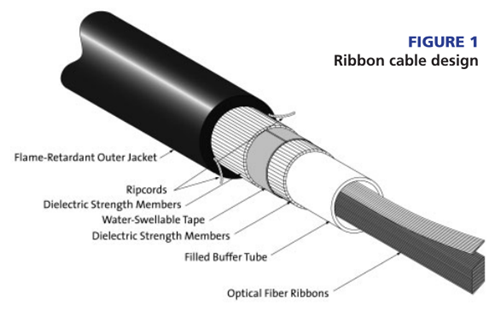
Data center backbones are migrating to higher cabled fiber counts to meet the increasing system bandwidth needs. Network designers used to specify tight-buffered and loose-tube cable designs for these backbone applications. But in today’s networks, designers are turning to ribbon cable designs as they provide the highest connectivity density relative to cable size.
This cable design characteristically consists of 12 to 216 fibers organized inside a central tube. The 12-fiber ribbons are readily accessible and identifiable with ribbon identification numbers and TIA-598 compliant fiber color coding. For indoor application, it used specially formulated flame-retardant outer jackets, which allow the cable design to meet the requirements of the NFPA-262 flame test for ribbon plenum cables and the requirements of the UL-1666 flame test for ribbon riser cables. Like the stranded loose tube cable, completely gel-free designs are available. See Figure 1.
The second method to deploy MTP connectorized ribbon cable involves using an MTP inter-connect. In this method, an MTP connectorized harness cable is plugged into the front of the panel. This MTP connectorized harness is a ribbon interconnect cable terminated with MTP connectors on both ends, or can be terminated with single fiber connectors on one end. The other end of the harness is typically run to a network device or to a patch panel. This method of deployment for applications will use parallel transmissions, such as Infiniband. Because there is no module with single fiber connectors to plug into for testing, there is a method to test the MTP connectorized ribbon cable link. This link-loss test method uses a 3-jumper reference. We’ve outlined the link-loss test method for MTP connectorized ribbon cables without modules below.
Posted by: angelina at
02:38 AM
| No Comments
| Add Comment
Post contains 693 words, total size 6 kb.
January 04, 2016
Posted by: angelina at
04:02 AM
| No Comments
| Add Comment
Post contains 144 words, total size 1 kb.
32 queries taking 0.0433 seconds, 101 records returned.
Powered by Minx 1.1.6c-pink.

