



July 29, 2016
Ethernet cables are the standard cables used for almost all purposes that are often called patch cables or fiber jumper. In an article "How to Choose Ethernet Cableâ€, we know that Ethernet cables can be categorized into many types, like straight-through and crossover Ethernet cable, UTP or STP, Cat5 or Cat6, etc. But we know little about the pins and wiring in Ethernet cables and RJ45 plugs.
RJ-45 conductor cable contains 4 pairs of wires, each consisting of a solid colored wire and a strip of the same color. There are typically two wiring standards for RJ-45 wiring: T-568A and T-568B. What do they mean, and why they are important? This post will discuss the color diagram of straight-through and crossover Ethernet cable to help you figure out.
Straight-Through and Crossover Cables
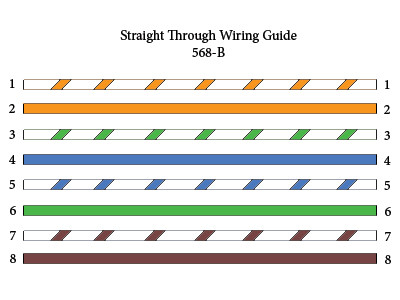
Straight-through refers to the Ethernet cables that have the pin assignments on each end of the cable—Pin 1 connector A goes to Pin 1 on connector B, Pin 2 to Pin 2 etc. Straight-through wired cables see in Figure 1 are most commonly used to connect a host to client. For example, the straight-through wired cat5e patch cable is used to connect computers, printers and other network client devices to the router switch or hub (the host device in this instance).
While an crossover cables are similar with straight-through cables, except that TX and RX lines are at opposite positions on either end of the cable, in other words, Pin 1 on connector A goes to Pin 3 on connector B. Pin 2 on connector A goes to Pin 6 on connector B ect. Crossover cables are most commonly used to connect two hosts directly.
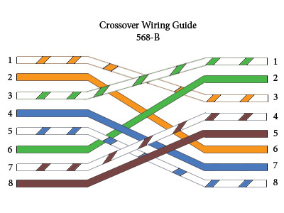
What’s more, the color code diagram of these two cables are different. To create a straight-through cable, you will use either T-568B or T-568A on both ends, while to create a cross-over cable, you will wire T-568A on one end, and T-568B on the other end.
T-568B and T-568A Standard
T-568A and T-568B are the two wiring standards for RJ-45 connector data cable specified by TIA/EIA-568A wiring standards document. T-568A standard ratified in 1995, was recently replaced by the T-568B standard in 2002. The difference between the two is the position of the orange and green wire pairs. It is preferable to wire to T-568B standards if there is no pre-existing pattern used within a building.
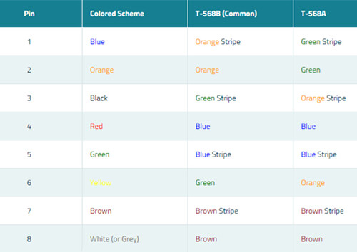
Both the T-568A and T-568B standard Straight-through cables are used most often as patch cords for your Ethernet connections. If you require a cable to connect two Ethernet devices directly together without a hub or when you connect two hubs together, you will need to use a Crossover cable instead.
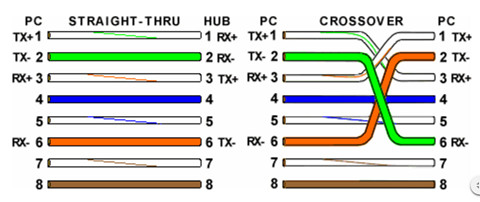
Looking at a T-568A UTP Ethernet straight-through cable and an Ethernet crossover cable in the above image with a T-568B end, we see that the TX pins are connected to the corresponding RX pins, plus to plus and minus to minus. You can also see that both the blue and brown wire pairs on pins 4, 5, 7, and 8 are not used in either standard. What you may not realize is that, these same pins 4, 5, 7, and 8 are not used or required in 100BASE-TX as well. So why bother using these wires, well for one thing its simply easier to make a connection with all the wires grouped together. Otherwise you’ll be spending time trying to fit those tiny little wires into each of the corresponding holes in the RJ-45 connector.
Conclusion
Ethernet cable color-coded wiring standard allows optical technicians to reliably predict how Ethernet cable is terminated on both ends so they can follow other technicians' work without having to guess or spend time deciphering the function and connections of each wire pair. There is no technical difference between the T568A and T568B wire standard, so neither is superior than the others.
Posted by: angelina at
07:18 AM
| No Comments
| Add Comment
Post contains 650 words, total size 5 kb.
July 27, 2016
The Cisco GLC-LH-SM optical transceiver, as one type of SFP transceivers, presents a huge change in the ease of incorporating fiber optic technology into enterprise networking. SFP transceivers does not need to be configured to begin function, and offers internal calibration to optimize data throughput. And, being hot swappable, it can be assured that other network components would keep online during the replacement of the SFP transceivers. Cisco GLC-LH-SM is 1000BASE-LX/LH SFP, which is widely used in optical network systems. High-quality Cisco Compatible GLC-LH-SM is offered only $7 at Fiberstore. Here is what you need to know about Cisco GLC-LH-SM.
Features of GLC-LH-SM
Cisco GLC-LH-SM is the 1000BASE-LX/LH SFP compatible with the IEEE 802.3z 1000BASE-LX standard. Unlike other Cisco SFP transceivers that can operate either on single mode or multimode fibers, GLC-LH-SM can support on standard single mode fiber-optic with a link span of up to 10 km and up to 550 m on any multimode fibers. This industry-standard Cisco Small Form-Factor Pluggable (SFP) is a hot-swappable input/output device that plugs into a Gigabit Ethernet port or slot, linking the port with the network.
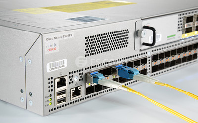
The GLC-LH-SM, can be used and interchanged on a wide variety of Cisco products and can be mixed in combinations of 1000BASE-SX, 1000BASE-LX/LH, or 1000BASE-ZX on a port-to-port basis Cisco Catalyst 6500 or 7600 Series Supervisor Engine 720.
Advantages of Cisco GLC-LH-SM Optics
Generally speaking, widespread adoption of fiber optic networking has been extremely high precision demands and delicate construction that came along with the media; but fiber optic cables made of glass-like material can easily damage. Also, the interfaces on either end of the cable have often been required to be very expensive, highly complex transceivers that required a large amount of intricate configuration to perform optimally, which becomes the main obstacle of the widespread adoption of fiber optic networking.
However, with Cisco GLC-LH-SM fiber optic transceivers, the challenges are a thing of the past. Here are three ways that the GLC-LH-SM transceivers make fiber optic networking very possible.
1. There is no need for Cisco SFP transceivers to configuring before function, and it also offers internal calibration to optimize data throughput.
2. Another unique advantage of fiber optics is that these SFP transceivers are truly hot swappable, which means a transceiver failure can be solved by simply replacing a new one, then you network is back online and ready to go.
3. GLC-LH-SM fiber optics also has a single or multimode operations. Single mode allows data transmission over distances exceeding 10km, useful for very large research facilities, hospitals, or university campuses. And multimode fibers open the data floodgates, giving you maximum throughput upwards of 1.25 Gbps so that this transceiver can meet your needs whether a network solution that covers a long distance, or the huge bandwidth fiber optic.
FS.COM Compatible Cisco GLC-LH-SM Optics
For the past decade, we have led the industry in manufacturing and delivering world-class products that improve the way we communicate. Cisco compatible GLC-LH-SM is offered at the minimum price of $7 in FS.COM, which is much lower than that in Amazon ($34).
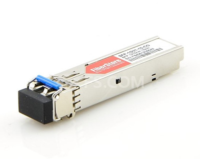
FS.COM 1000BASE-LX/LH SFP can be used in Gigabit Ethernet, Fibre Channel, switch to switch interface, switched backplane applications, router or server interface and other optical transmission systems. Besides the compatible 1000Base-LX/LH SFP modules, we also provide the 1000BASE-EX (like Cisco GLC-EX-SMD), 1000BASE-SX (like Cisco GLC-ZX-SM), 1000BASE-BX (like Cisco GLC-BX-D) and so on.
Conclusion
Fiber optic technology has been around for several decades now, and is sure to be the future transmission media for network backbone and other high-demand applications. Cisco GLC-LH-SM, as an old established Cisco SFP transceivers, wins large market share in telecom field. Cisco GLC-LH-SMD is a new type of GLC-LH-SM with a added function of DOM, which you can also buy it from the market.
Posted by: angelina at
03:02 AM
| No Comments
| Add Comment
Post contains 635 words, total size 5 kb.
July 20, 2016
Fiber optical technology typically presumes a service life of nearly 30 years. It is not a revolutionary or a new technology, in fact it is only about carrying light from one point to another. The questions that frequently asked around the industry are the art of mysticism, thus this post has collected questions made by professional during seminars, forum and projects. Solutions are also provided respectively to help readers to form the general understanding of this system.

Do signals really travel faster in fiber optics?
The speed here doesn’t refer to the the speed of signals in fiber optic cable, but the bandwidth potential of the fiber. Because you know that the speed of light in glass is about 2/3 C, but you might be surprised to know that signals in UTP (unshielded twisted pair) cables like Cat 5e travel at about the same speed (2/3 C). Coax, meanwhile, has a faster NVP (nominal velocity of propogation), about 0.9C, due to it's design.
What do I need for connecting Optic Fiber Cable to a Cat 5 Cable?
You need a media converter available from a number of companies for nearly $100-200.
Do you see any real serious problems in splicing together fiber cables from different manufacturers, as long as the cable is manufactured to the same specifications?
No, not as long as they are the same type and size, for example, multimode 62.5/125 or 50/125 and single mode should be normal (non-dispersion shifted) or dispersion shifted. Some single mode fibers are made for 1300 nm only, 1550 nm only or both, and they should not be mixed. Note that there are some other single mode fibers that have special coatings that cannot be mixed with others. Therefore you are supposed to ask your fiber vendors, splicer supplier or try it first before going into the field!
Will a single mode connector work on multi-mode cable?
The answer is maybe you can use SM connectors on MM but not the reverse. SM connectors are made to tighter tolerances—as is SM fiber—so the ferrule hole may be too small for some MM fibers. MM connectors have bigger holes for the fiber and will have high loss (>1dB) with SM. Also MM connectors may not be PC (physical contact) polish - terrible for return loss. MM fiber may not fit the smaller hole in SM connectors.
If you have a 50 micron fiber backbone, can you use 62.5 fiber jumpers on each end?
NO! On the receiver end it is OK, but on the transmitter end, the larger core of 62.5 into smaller 50 micron fiber will have fiber losses of 2-4 dB.
What is your view on using fiber optic connectors? Is it a better terminating method than fusion splice?
Of all the SFF (small form factor connectors), LC connector is the one that has become the most popular. In fact, it is the de facto standard connector for gigabit and 10 gigabit networks. Indeed the design is very well thought out. The smaller ferrule of a LC to LC fiber cable is easy to polish well and has excellent mating performance—which leads to low loss and back reflection. It is also easy to terminante and test.
What is the theoretical lifetime of optical fiber and optical fiber cables?
There is no "theoretical lifetime†of optical fibers. There is no industry accepted "wear out†mechanism for optical fiber. So there is no physical-chemical reach to test and accelerate in order to predict an eventual failure mechanism and corresponding failure reaction rate.
Can the same fiber-optic transceivers that are used with Om3 fiber, like SFP+ pluggable modules, be used with Om4 fiber or are there new transceiver types that need to be used?
Yes, you can use the same fiber optic transceivers for both Om3 and Om4 fibers because the two fiber types are basically the same except that Om4 fiber has higher bandwidth. The IEEE 10G Ethernet standard states that 300-meter Om3 and 400-meter Om4 link lengths are supported with 10GBase-S-compliant transceivers.
Which cabling media are typically used in data center/storage area network (SAN) environments?
There are a variety of different types of cabling media deployed in the data center. Multimode and single mode fiber, direct attach connection (DAC) cables, CX4 copper cables, and Category 6A twisted-pair all have a place.
The cabling type that is deployed is typically based on port type, cost, and distance. Distance is dictated by the architecture of the data center, which can be centralized/direct connect, distribution/top-of-rack switching, zoned distribution, or a combination of these.
Fiber is often deployed to connect top-of-rack switches to an aggregation switch at the end of the row or in another location, in centralized architectures for the "home runs," and in zoned distribution architectures. Multimode fiber supports all distances in the typical data center, such as connecting top-of-rack switches within rows back to an aggregation or core layer, or connecting servers to end-of-row switches. For larger data centers, where MM fiber patch cords may not suffice, single mode fiber can enable much longer distances. Single mode fiber can also be deployed within the row as a strategy for future applications that might use multiple-wavelength technologies. Another alternative to traditional cable and connector deployments for connectivity between servers and switches within the rack is to use direct attached cables connecting to SFP+ ports.
Is fiber more difficult to install than copper?
It depends on the comfort level and training of the technicians. Because fiber has been accepted as the standard choice for communications backbones for many years, today's installers are generally comfortable with the technology, but there is a learning curve for those just starting out. Of course, the same could be said of new generations of copper cabling. The new generation high-speed copper cables require more stringent and time-consuming installation techniques than were required in the past.
Compared to newer grades of copper cable, fewer regulations exist on the methods by which optical cable is pulled and terminated. In addition, there is no need to worry about the location of EMI/RFI sources during installation. Also, with fiber cables, there are no requirements for mitigating techniques when migrating to 10GbE and higher data rates as there are with UTP copper media.
Posted by: angelina at
06:52 AM
| No Comments
| Add Comment
Post contains 1045 words, total size 8 kb.
July 18, 2016
In response to the increasing bandwidth demands facing data centers, network designers are paving the way for the introduction of 40Gbqs operations. Owing to this, telecommunication vendors continuously expand the portfolio of innovative parallel fiber optic transceivers to increase the 40G performance, resulting in 40G QSFP+ transceivers becoming the shining star on the market. 40G QSFP+ 40GBASE-iSR4 optics is the newly evolved products for 40G connectivity, but opportunity always besides with challenges. As people are so concerned about the future of their network, understanding the 40GBASE-iSR4 QSFP+ will be helpful for future high-performance Ethernet needs.
Why Move to 40G Ethernet Network
The volume of digital information flowing through data network develops at an ever increasing rate day by day. So the growth of cloud computing, server virtualization and the trend toward network convergence is forcing today’s networks to be more efficient and faster than ever. 1Gbps Ethernet access links have been replaced by 10Gbps links due to the increases in server utilization obtained through Virtualization. To keep up, higher performance switching hardware is needed to provide sufficient I/O (Input/Output) bandwidth to avoid blocking. In order to meet this demand, many newer access switches could support 48 ports of 10G Ethernet for connection to downstream servers, and 2 or 4 ports of 40G Ethernet for connection to the core switches. These 40G interconnects are implemented by using QSFP+ transceivers and could provide sufficient bandwidth to enable fully non-blocking switch fabrics.
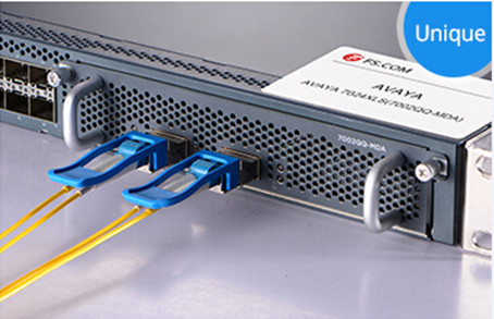
QSFP+ is featured with various advantages like delivering excellent high speed optical/electrical performance coupled with low power dissipation. In addition, with bundled fiber cables and MPO connectors, the port density of QSFP+ modules is triple that of SFP+ modules. Moreover, the power consumption is reduced from 1000 mW maximum per lane for SFP+ to 375 mW maximum per lane for QSFP+. 40GBASE-iSR4 QSFP+ module like AFBR-79EIDZ is not only 40Gb Ethernet compliant, but also inter-operable with any 10GBASE-SR compliant transceiver at link distances up to 100 meters over OM3 multimode fiber. The letter "i†in 40GBASE-iSR4 QSFP+ refers to the ability of inter-operation. AFBR-79EIDZ see in Figure 1 is Avago 40GBASE-iSR4 QSFP+ transceiver available on the market. Just as any other modules, this Avago QSFP+ iSR4 is designed to be fully compatible with the 40GBASE-SR4 specification. It’s capable of inter-operating with legacy 10GBASE-SR transceivers.
40GBASE-iSR4 QSFP+—an Cost-Effective Solution
40GBASE-iSR4 QSFP+ transceiver was released to tackle the issue of an overload condition when connecting a 40GBASE-SR4 transmitter to a 10GBASE-SR receiver. It is intended to be fully compliant to the 40GBASE-SR4 specification but with a lower maximum transmit optical output power. The maximum specified output power has been lowered from +2.4 dBm to -1 dBm allowing it to interface with 10GBASE-SR receivers without fear of overload.
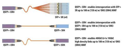
The VCSEL design combined with superior laser programming and control algorithms allow for a reduction in the module maximum specified optical output power without compromising any of the module high speed electro-optic performance. And the result (see in Figure 2) is a fully compliant 40GBASE-SR4 module like QSFP-40G-SR4 which can interoperate with legacy 10GBASE-SR transceivers. For further understanding of the 40GBASE-iSR4 optics, it is advisable for you to take a glance at the development of it.
Standardization of 40GBASE-iSR4
The release of IEEE 802.3ba-2010 standard for 40G Ethernet specifies the optical and electrical requirements for various physical layer link implementations. The 40GBASE-SR4 PMD (physical medium dependent) variant defines a 4-lane parallel optical interconnect for operation over OM3 multimode fiber with transmission distance up to 100 meters. Each of the four lanes works at a data rate of 10.3125 Gbps which is the same serial bit rate that was defined for 10G Ethernet links.
The 40GBASE-SR4 PMD addresses the need for 40Gbps interconnects in the data center. It takes advantage of the widely-deployed and low-cost 850nm VCSEL (vertical cavity surface emitting laser) technology. Because each of the 4 lanes in 40GBASE-SR4 have the same serial bit rate of 10G Ethernet link, there is an opportunity for switching hardware vendors to utilize 40GBASE-SR4 as 4 separate 10G Ethernet interconnects.
Challenge Hindering the Development
The standard of 40GBASE-SR4 provides an opportunity to further address the growing need for bandwidth. It is not defined to be backward compatible with the preceding 10G Ethernet short reach interconnect standard. Although both 40G Ethernet and 10G Ethernet included a PMD definition for short reach VCSEL based optical links operating at 10.3125 Gbps per lane, interoperability cannot be guaranteed.
The following analysis of 40GBASE-SR4 and 10GBASE-SR specifications tells why inter-operability cannot be guaranteed over all specified operating conditions.
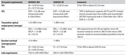
From the above chart, we could see that many of the transmitter and receiver specifications governing the 10GBASE-SR standard are equal or more stringent than those for 40GBASE-SR4 standard. This is not surprising because the 40GBASE-SR4 specification is written to cover transmission links up to 100 meters, while the 10GBASE-SR specification is intended to satisfy a maximum transmission link length of 300 meters over OM3 multimode fiber. Except the distance, the main specification gap preventing guaranteed inter-operability relates to receiver overload.
Summary
40GBASE-iSR4 QSFP+ proves itself as a suitable solution for designers to mount their network capacity. QSFP+ iSR4 optics is able to support standard 40G Ethernet links up to 100 meters over OM3 and 10GBASE-SR links over the same distances.
Posted by: angelina at
03:45 AM
| No Comments
| Add Comment
Post contains 881 words, total size 7 kb.
July 14, 2016
Ethernet cable is used to connect devices on local area networks (switch, router or hub), which is one of the most popular forms of fiber jumper cables used on wired networks. Ethernet cables are typically classified into sequentially numbered categories based on different specifications, such as cat5, cat5e, cat6, etc. What are the differences between these category Ethernet cable and how can you know when to use unshielded, shielded, stranded, or solid cable? This article will help you decide.
Category Ethernet Cable Difference
The Cat3, Cat4, Cat5, Cat5e, Cat6, and Cat7 are the abbreviation for the category number that defines the performance of UTP (Unshielded Twisted Pair) type of cable used for Ethernet wiring outlined by the Electronic Industries Association (EIA) standards. The differences in these cable specifications is not easy to identify. However, as the category number gets higher, so does the speed and Mhz of the wire. The following image shows a comparison between Cat5, Cat6 and Cat6 UTP cables.
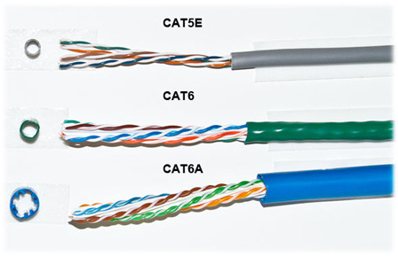
Besides the speed and hertz, there are two main physical differences between Cat5 and Cat6 cables, the number of twists per cm in the wire, and sheath thickness. It is known that cable twisting length is not standardized, but typically there are 1.5-2 twists per cm in Cat5e and 2+ twists per cm in Cat6. The amount of twists per pair is usually unique for each cable manufacturer. From the above picture, you can see that no two pairs have the same amount of twists per inch. And Cat5e cable has the thinnest sheath, but it also was the only one with the nylon spline. The nylon spline can help eliminate crosstalk, the thicker sheath protects against near end crosstalk (NEXT) and alien crosstalk (AXT) which both occur more often as the frequency (Mhz) increases.
Nowadays Category 5 cable was mostly replaced with Category 5 Enhanced (Cat5e) cable which did not change anything physically in the cable, but instead applied more stringent testing standards for crosstalk. While Category 6 was revised with Augmented Category 6 (Cat6a) which provided testing for 500 Mhz communication (compared to Cat6’s 250 Mhz). The higher communication frequency eliminated alien crosstalk (AXT) which allows for longer range at 10 Gb/s.
Shielded (STP) vs. Unshielded (UTP)
All Ethernet cables are twisted pair, but they are created equally. Telecom vendors rely on shielding to further protect the Ethernet cable from interference, thus the shielded twisted cable (STP) is more suitable for area with high interference and running cables outdoors or inside walls. Unshielded twisted pair however, can easily be used for cables between your computer and the wall. Technically the picture below shows a Screened STP cable (S/STP).
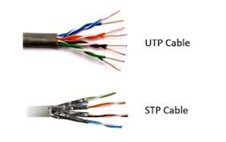
There are different methods to shield an Ethernet cable, but typically it involves putting a shield around each pair of wire in the cable. This protects the pairs from crosstalk internally. Manufactures can further protect cables from alien crosstalk but screening UTP or STP cables.
Solid vs. Stranded
Solid or stranded refer to the actual copper conductor in the pairs. Of an Ethernet cable. Solid conductor uses 1 solid wire per conductor, so in a 4 pair (8 conductor) roll, there would be a total of 8 solid wires. Stranded conductor uses multiple wires wrapped around each other in each conductor, so in a 4 pair (8 conductor) 7 strand roll, there would be a total of 56 wires.
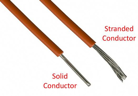
Each type of conductor (see in the above picture) can be utilized in different applications. Stranded cable is more flexible and should be used at your desk or anywhere you may be moving the cable around often. Solid cable is not as flexible as stranded cable, but more durable which makes it ideal for permanent installations as well as outdoor and in walls. Stranded wire are generally made with patch leads with connectors on the either end like LC to SC patch cord.
Conclusion
Due to the electrical transmission characteristics, a single Ethernet cable like an electric power cord, can extend only limited distances. At the end of the article, you may know when to choose STP, UTP, stranded or solid cables. Note that if you're cabling a mission critical system or you want your network to be future proof, go for the CAT6 cables, but for the average home or small office network CAT5 or CAT5e will be just fine.
Posted by: angelina at
08:28 AM
| No Comments
| Add Comment
Post contains 727 words, total size 6 kb.
July 12, 2016
Fiber optics, with its high bandwidth capacities and low attenuation characteristics, is considered to be the ideal building equipment in the telecommunication field. Depending on the type of application and the reach to be achieved, various types of optical fiber may be considered and deployed. This article is devoted to provide solutions to the questions about fiber optic cables. After going through the whole passage, you might form a basic understanding of optical cables.
What Is an Optical Fiber?
Core and cladding are the two main elements of an optical fiber. The core as shown in the image below, is the axial part of the optical fiber made of silica glass, which is the light transmission area of the fiber. The cladding is the layer completely surrounding the core. The refractive index of the core is higher than that of the cladding, so that light in the core strikes the interface with the cladding at a bouncing angle, gets trapped in the core by total internal reflection, and keeps traveling in the proper direction down the length of the fiber to its destination.
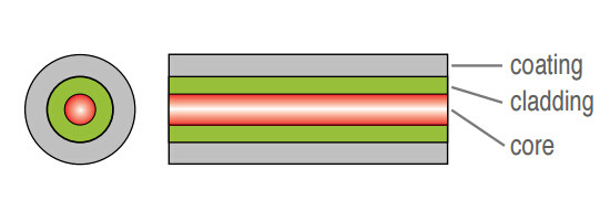
There is usually another layer, called a coating surrounding the cladding that typically consists of protective polymer layers applied during the fiber drawing process, before the fiber contacts any surface. As we all known, the most typical types of fiber optic cable are MM fiber patch cords and single mode fiber optic cables.
How Do Fiber Optics Work?
Fiber optics use light pulses to transmit signals from one end to another. Light passes through the optical cable, bouncing off the cladding until it reaches the other end of the fiber channel, which is called total internal reflection. The diameter of the core corresponds directly with the angle of reflection.
As this diameter increases, the light requires more reflections and a greater amount of time to travel a given distance. For example, single mode fiber optic cable has a smaller diameter core which makes itself suitable for long distance, higher bandwidth runs. Multimode fiber, however, has a larger diameter core and is more commonly used in shorter cable runs.
What You Need to Know About Optical Fiber?
Attenuation and WavelengthLight is gradually attenuated when it is propagated along the fiber. The attenuation value is expressed in dB/km. It is a function of the wavelength (λ), meaning that the operating wavelength to transmit a signal in an optical fiber is not any wavelength. It corresponds to a minimum of attenuation.
The typical operating wavelengths that light sources have been developed for are 850 nm and 1300 nm in multimode, and 1310 nm and 1550 nm in single mode. For a 850 nm operating wavelength, there is a 3dB light attenuation after 1 km propagation. 3 dB means that half of the light has been lost.
Bandwidth
Bandwidth is a measure of the data-carrying capacity of an optical fiber. For example, a fiber with a bandwidth of 500 MHz.km (Mega-hertz kilometer) can transmit data at a rate of 500 MHz along one kilometer. Bandwidth in single mode fibers is much higher than in multimode fibers.
How to Link Two Optical Fibers?
Fusion SpliceThis operation usually needs a fusion splicer to accomplish the process. In this method, optical technician directly links two fibers together by welding with an electric arc, by aligning best possible both fiber cores. Compared with other method, this linking method is fast and relatively simple to make. And the light loss generated by the welding, due to an imperfect alignment of the cores, remains very weak.
However, just as the coin has two sides, this link method has drawbacks. In spite of a protection of fusion by a heat-shrinkable tube, this type of link is relatively fragile. It is a permanent link. What’s worst, the fusion splicer is usually very expensive.
Use of Connectors
In this case, it is necessary to terminate a connector at each end of the fibers to be connected. The two fibers can then be connected by connecting the two connectors together. The following picture shows a SC fiber patch cord.
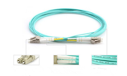
Just as the following picture shows, this type of connection is robust. The type of connector can be chosen according to the application field of the system. Unlike fusion splice, this connection is removable. It is possible to connect and disconnect two fibers hundreds to thousands times without damaging the connectors. But the implementation is longer than fusion, and requires an experiment as well as specific tools. Furthermore, the light loss due to connection is higher than in the splicing solution.
Why to Choose Fiber Optics?
The main advantages of fiber optics are the followings:- Lower loss: Optical fiber has lower attenuation than copper conductors, allowing longer cable runs and fewer repeaters.
- Increased bandwidth: The high signal bandwidth of optical fiber provides a significantly greater information-carrying capacity. Typical bandwidths for multimode fibers are between 200 and 600 MHz.km, and > 10 GHz.km for singlemode fibers. Typical values for electrical conductors are 10 to 25 MHz.km.
- Immunity to interference: Optical fibers are immune to electromagnetic and radio frequency interference and also emit no radiation themselves.
- No detection: Standard fiber optic cables are dielectric, so they cannot be detected by any type of detector.
- Electrical isolation: Fiber optics allows to transmit information between two points at two different electrical potentials, and also next to high voltage equipments.
- Decreased size and weight: Compared to copper conductors of equivalent signal-carrying capacity, fiber optic cables are easier to install, require less duct space, and weight about 10 to 15 times less.
Conclusion
The Internet nowadays is largely based around optical fiber. For those who do not understand fiber optics, they will have confusion and misconceptions when working with fiber optic networks. This article probably will not make you an optical engineer, but it will guide you to touch on a little bit of every topics, from the theoretical to the practical even if you aren’t designing optical networks.
Posted by: angelina at
07:54 AM
| No Comments
| Add Comment
Post contains 999 words, total size 8 kb.
July 07, 2016
Optical technology nowadays has made huge progress to meet the growing requirement for high-density multifiber applications in telecommunication field. Fiber optic splitter, as an indispensable equipment for fiber optic network, enables signals on an optical fiber to be distributed among two or more fibers. Optical cable splitter typically can be divided into FBT (Fused Biconical Taper) splitter and PLC (Planar Lightwave Circuit) splitter. Each type has advantages and disadvantages when deploying them in a passive optical network. This article will guide you to form a basic knowledge about fiber optic splitter, especially FBT splitter and PLC splitter.
Fiber Optic Splitter
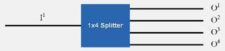
Optical splitter, also known as a beam splitter, is based on a quartz substrate of an integrated waveguide optical power distribution device, which is used to split the fiber optic light evenly into several parts at a certain ratio. Since splitters contain no electronics nor require power, they are an integral component and widely used in most fiber optic networks. The diagram below shows how light in a single input fiber can split between four individual fibers (1x4).
Optical splitters are manufactured commonly in two types according to its working principle—FBT (Fused Biconical Taper) splitter and PLC (Planar Lightwave Circuit) splitter. Splitters can be built using a variety of single mode fiber patch cables and multimode optical fibers and with most connector types for various applications.
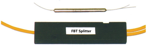
FBT Splitter—FBT is a traditional technology that two fibers are typically twisted and fused together while the assembly is being elongated and tapered. The fused fibers are protected by a glass substrate and then protected by a stainless steel tube, typically 3mm diameter by 54mm long. FBT splitters are widely accepted and used in passive optical networks, especially for instances where the split configuration is not more than 1×4. The slight drawback of this technology is when larger split configurations such as 1×16, 1×32 and 1×64 are needed. The following picture shows a FBT splitter with a split configuration of 1×2.
PLC splitter—A PLC splitter is a micro-optical component based on planar lightwave circuit technology and provides a low cost light distribution solution with small form factor and high reliability. It is manufactured using silica glass waveguide circuits that are aligned with a V-groove fiber array chip that uses ribbon fiber. Once everything is aligned and bonded, it is then packaged inside a miniature housing. PLC Splitter has high quality performance, such as low insertion loss, low PDL (Polarization Dependent Loss), high return loss and excellent uniformity over a wide wavelength range from 1260 nm to 1620 nm and have an operating temperature -40°C to +85°C. The following picture shows a PLC splitter connected with LC LC single mode patch cord.
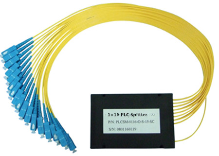
Advantages and Disadvantages of FBT and PLC splitters1. FBT—Fused Biconical Splitter
FBT splitter is one of the most common splitters, which is widely accepted and used in passive networks. FBT splitter is designed for power splitting and tapping in telecommunication equipment, CATV network, and test equipment.
Advantages
- The product is well-known and is easy to produce, thus reducing cost of production.Splitter ratios can be customized.
- Can work on three different operating bands (850nm, 131 Onm, and 1550nm).
Disadvantages
- Restricted to its operating wavelength.
- Because of errors in equality insertion loss, the maximum insertion loss will vary depending on the split and increase substantially for those splits over 1:8.
- Because an exact equal ratio cannot be ensured, transmission distance can be affected.
- High temperature dependent loss (TDL). The operating temperature range is 23 °F- 167 °F. Any changes in temperature can affect the insertion loss.
- The larger the split, the larger the encapsulation module.
- Susceptible to failure due to extreme temperatures or improper handling.
2. PLC—Planar Lightwave Circuit Splitter
PLC splitter is a hot research at home and abroad today, with a good prospect of application, which is used to distribute or combine optical signals. It is based on planar lightwave circuit technology and provides a low cost light distribution solution with small form factor and high reliability.
Advantages
- Suitable for multiple operating wavelengths (1260nm–1650nm); unstinted.
- Equal splitter ratios for all branches.
- Compact configuration; smaller size; small occupation space.
- Good stability across all ratios.
- High quality; low failure rate.
- Complicated production process.
- Costlier than the FBT splitter in the smaller ratios.
Conclusion
Similar in size and outer appearance, PLC and FBT splitters provide data and video access for business and private customers, but internally the technologies behind these types vary, thus giving service providers a possibility to choose a more appropriate solution.
Posted by: angelina at
02:24 AM
| No Comments
| Add Comment
Post contains 755 words, total size 7 kb.
July 01, 2016
Fiber optical cable is the composite material, typically consists of a hair-thin glass used to transmit pulses of light instead of electrical signals. Thus the termination must be much more precise. Compared with copper cables end with RJ connectors, fiber optic connectors must align microscopic glass fibers perfectly to make metal to metal contact. There are many different types of fiber connectors, they share similar design characteristics, such as LC to LC patch cord, single mode LC to ST fiber patch cable, single mode fiber ST to SC patch cord, single mode fiber cable with LC connector, etc. Nowadays most cables are ended with the same connector, which poses a problem for users to sort through cables and connectivity options. That’s why this article is provided here to help out the illustration of fiber optics and optical connectors.
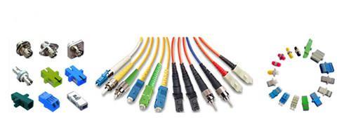
Internal Structure of Optical Connector
Fiber optic connector terminates the end of fiber optic cable, enabling quicker connection and disconnection than splicing. As noted before, optical connector has to be aligned properly to the microscopic glass fibers completely in order to allocate for communication. There are three major components of a fiber connector: the ferrule, the connector body, and the coupling mechanism.
- Ferrule
It is a thin structure that is actually used to holds the glass fiber, which has a hollowed-out center that forms a tight grip on the fiber. Ferrules are usually made from ceramic, metal, or high-quality plastic, and typically will hold one strand of fiber.
- Connector Body
This is a plastic or metal structure that holds the ferrule and attaches to the jacket and strengthens members of the fiber cable itself.
- Coupling Mechanism
This is a part of the connector body that holds the connector in place when it gets attached to another device. It may be a latch clip, a bayonet-style nut, or similar device.
Different Types of Fiber Optic Connectors
To sum up, there are nearly 100 fiber optic connectors on the market, but only a few are available that was lower loss, lower cost, easier to terminate. Optical connectors like LC connector, SC connector, ST connector, FC connector, RJ45 connector, MT-RJ connector are the representative that will be present to you.
- SC Connector
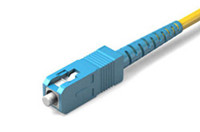
SC or square connector, was developed by Nippon Telegraph and Telephone on the market, slowly grew in popularity as manufacturing cost went down. Now it is becoming increasingly popular in single-mode fiber optic cable, analog CATV, GPON, GBIC. SC is a snap (push-pull coupling) connector with a 2.5mm ferrule diameter that operates on the standard IEC 61754-4. The connector’s outer square profile together with its snap coupling mechanism that allows greater connector packaging density in instruments and patch panels. The SC fiber patch cord is ideally suited for datacoms and telecoms applications including point to point and passive optical networking.
- LC Connector
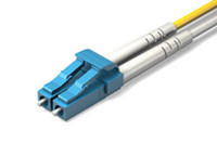
LC or Lucent Connector, is a push-pull, small form factor connector that uses a 1.25mm ferrule, half the size of the SC. Due to the combination of small size and latch feature, LC connector is ideal for high-density connections and usually utilized in SFP, SFP+, XFP, and single-mode QSFP+ transceivers. Along with the development of LC compatible transceivers and active networking components, it will continue to grow in the FTTH arena.
- FC Connector
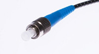
FC or Ferrule Connector., is a round, threaded fiber optic connector that was designed by Nippon Telephone and Telegraph in Japan. The FC connector is applied for single-mode fiber and polarization-maintaining optic fiber. The FC is a screw type connector with a 2.5mm ferrule, which was the first fiber optic connector to use a ceramic ferrule. However, FC is becoming less common and gradually replaced by SC and LC connectors because of its vibration loosening and insertion loss.
- ST Connector
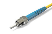
ST or Straight Tip, was developed by AT&T shortly after the arrival of the FC. They may be mistaken for one another, but ST uses a bayonet mount other than a screw thread. And you have to make sure SC connectors are seated properly owing to its spring-loaded structure. SC is mainly used in multimode fiber optic cable, campuses and buildings.
- RJ-45 Connector
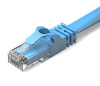
RJ-45 connectors are physically wider than the RJ-11/12 connectors used for telephone. In network applications, RJ-45 cable assemblies are used to connect from a patch panel to a network switch, and also to connect a computer's NIC to a data port.
- MT-RJ Connector
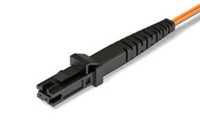
The MTRJ connector closely resembles an RJ-style modular plug, even getting part of its name from the resemblance. It is covered in the TIA connector intermateability standard FOCIS-12 (TIA-604-12). MT-RJ is a duplex connector with both fibers in a single polymer ferrule. It uses pins for alignment and has male and female versions. Multimode only, field terminated only by prepolished/splice method.
Conclusion
Whether you are about to install a new fiber optic network, or perhaps you are maintaining on an existing one, you are supposed to have a basic knowledge about fiber optics and optical connector. This article simply illustrates the most commonly used fiber optic connectors on the market to help you sort through the optical connectors.
Posted by: angelina at
03:16 AM
| No Comments
| Add Comment
Post contains 851 words, total size 7 kb.
32 queries taking 0.0523 seconds, 91 records returned.
Powered by Minx 1.1.6c-pink.

