



June 07, 2016
FTTH (Fiber to the Home) network compared with technologies now used in most places, increases the connection speeds available for residences, apartment building and enterprises. FTTH network is the installation and use of optical fiber from a central point known as an access node to individual buildings. The links between subscriber and access node are achieved by fiber jumper cables. Loose-tube and tight buffer cables are commonly used to transmit signals with high speed, which are capable of supporting outdoor or indoor environment. Is there a cost-effective solution that can support both indoor and outdoor environment in FTTH network? To answer this, the construction and comparison of loose tube cable and tight buffer cable will be introduced in the following article.
Loose-Tube and Tight-Buffer Cable
The "buffer†in tight buffer cable refers to a basic component of fiber optic cable, which is the first layer used to define the type of cable construction. Typically a fiber optic cable consists of the optical fiber, buffer, strength members and an outer protective jacket (as showed in Figure 1). Loose-tube and tight-buffer cables are two basic cable design. Loose-tube cable is used in the majority of outside-plant installations, and tight-buffered cable, primarily used inside buildings.
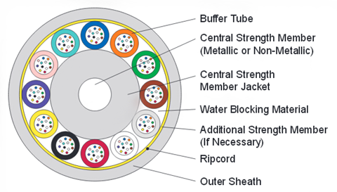
Loose-tube cable consists of a buffer layer that has an inner diameter much larger than the diameter of the fiber see in the following picture. Thus, the cable will be subject to temperature extremes in the identification and administration of fibers in the system. That’s why loose-tube cables are usually used in outdoor application. The loose-tube cables designed for FTTH outdoor application are usually loose-tube gel-filled cables (LTGF cable). This type of cable is filled with a gel that displaces or blocks water and prevents it from penetrating or getting into the cable.
Tight buffer cable using a buffer attached to the fiber coating is generally smaller in diameter than loose buffer cable (showed in Figure 2). The minimum bend radius of a tight buffer cable is typically smaller than a comparable loose buffer cable. Thus tight buffer cable is usually used in indoor application.
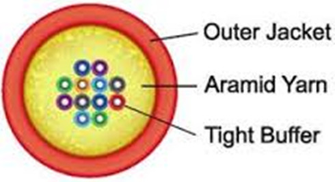
Tight buffered indoor/outdoor cable with properly designed and manufactured can meet both indoor and outdoor application requirements. It combines the design requirements of traditional indoor cable and adds moisture protection and sunlight-resistant function to meet the standards for outdoor use. Tight buffered indoor/outdoor cable also meets one or more of the code requirements for flame-spread resistance and smoke generation.
Choose Tight Buffer Cable for FTTH Network
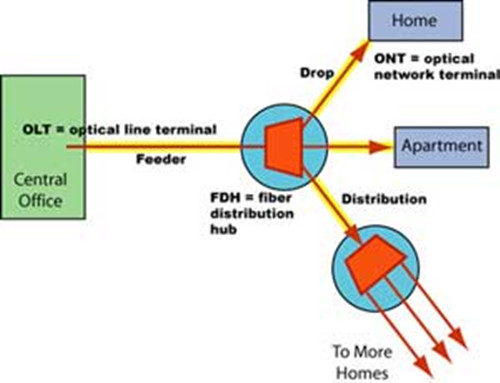
The inner construction of tight buffer indoor/outdoor cable have been introduced above. The following will explain why tight buffered indoor/outdoor cable is a better FTTH cabling solution. Figure 3 shows a clear structure of FTTH network.
Using the traditional choice of LTGF cables as the outdoor cable, there would be a conversion from one fiber type to another type, which includes prep work on the fiber, the need for splice tray, the routing of fibers in the tray, and other similar detail. Before termination and splicing, the gel of LTGF cable must be cleaned and the breakout point of the main cable must be blocked by some method to prevent oozing of the cable gel. In addition, this cable type must normally be terminated or spliced close to the cable entryway of a building to switch to indoor cable, as it generally incompatible with indoor fiber codes. This time consuming and labor intensive process adds hidden costs to install the LTGF cables.
However, using only tight buffer indoor/outdoor cable for FTTH is much more convenient and cost-effective. A tight-buffered indoor/outdoor cable can be used throughout the link, requiring no transitions at the building entryway. Tight buffer indoor/outdoor cable requires less care to avoid damaging fibers when stripping back the cable. The termination and splicing of these cables are easier than that of LTGF cables.
An important reason why choose tight-buffered indoor/outdoor cable for FTTH cable installation is the reliability of the overall system. Splicing are the weakest point in a FTTH network. With splicing, the bare fiber ends are open to dust, dirt, water, vapor, and handing which might reduce the fiber strength and increase brittleness. Choosing loose tube outdoor cable for FTTH, there will be splices after the conversion from one cable type to another type. The splices inside a building may be held in a cabinet that is open to the air, which might decrease the reliability of the FTTH network. Using the tight buffer indoor/outdoor cable could eliminate splicing and improve the installation reliability greatly.
Conclusion
This article has explained loose-tube and tight buffer indoor/outdoor cables. Network installer can run a single cable type and remove a transition point between the outside plant and the inside plant. At the same time, the reliability of the overall FTTH network can be increased greatly.
Posted by: angelina at
02:31 AM
| No Comments
| Add Comment
Post contains 807 words, total size 7 kb.
June 03, 2016
A smooth connection between cable and other optical devices allows the optical signals to pass with low attenuation and little return loss, which is vital for telecommunication network. Fiber optic pigtails, compared with the regular fiber jumper, is terminated with fiber optic connector at only one side of the cable, which are usually used with fiber optic management equipment like ODF, splice closures and cross cabinets. Today’s article will provide some detailed information about fiber optic pigtails.
What Is Fiber Optic Pigtail?
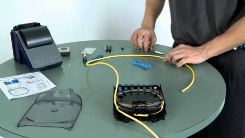
Fiber optic pigtail is also called bare fiber. It is a kind of optical cable terminated with fiber optic connectors at one side of the cable while leave the other side no connectors, so that the connector side can link to the equipment (eg. fiber converter or optical transceiver module) and the other side can be melted with optical fiber. In fact, fiber optic pigtail and patch cord are similar in structure, fiber optic patch cable is composed of a fiber optic cable terminated with connectors on both ends. Sometimes, we cut the fiber optic patch cord in the middle, strip its jacket and then end up with a pigtail. Figure 1 shows the process of fiber optic pigtail splicing.
Fiber optic pigtails are designed to meet or exceed all of the performance requirements for current and proposed applications. They are available in various optical connector type, single-mode and multimode fiber, as well as fiber counts and cable structure. Here is what you need to know about the classification of fiber optic pigtails.
Divided by the Optical Connectors
Commonly used fiber optic pigtails are available in SC, FC, LC, ST, MU, E2000 and MTRJ type.
LC Fiber Optic Pigtails: LC features the low cost and high precision 1.25mm outer diameter ceramic ferrules and highly favored for single mode applications. LC fiber optic pigtail use LC connector and suit for density installations.
SC Fiber Optic Pigtails: SC connector is a non-optical disconnect connector with a 2.5mm pre-radiused zirconia or stainless alloy ferrule. It is light weight and economic to use in different applications such as CATV, LAN, WAN, test and measurement. SC fiber optic pigtails are also a commonly used pigtail type in cable installation. The following picture shows a SC fiber cable (left) and SC fiber optic pigtail (right) .
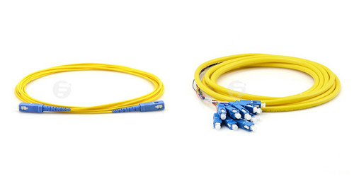
ST Fiber Optic Pigtails: ST fiber optic connector is the most popular connector for multimode fiber optic LAN applications. It has a long 2.5mm diameter ferrule made of ceramic (zirconia), stainless alloy or plastic. SC fiber optic pigtails are used in telecommunications, industry, medical and sensor fields.
FC Fiber Optic Pigtails: FC fiber optic pigtails use the metallic body FC fiber optic connectors. FC features the screw type structure and high precision ceramic ferrules. FC fiber optic pigtails and related products are known for the general and average applications.
MU Fiber Optic Pigtails: MU connector is called "mini SC†as it is only half size of the SC and are more popular in Japan. Applications of MU connectors include high-speed data communications, voice networks, telecommunications, and dense wavelength division multiplexing (DWDM). MU fiber optic pigtails use the MU connector that inherits the features and advantages of SC connector.
MT-RJ Fiber Optic Pigtails: MT-RJ fiber optic pigtails use the MT-RJ connectors that are specially designed for fast Ethernet. They are all duplex types with a mini ribbon fiber inside. MT-RJ inherit the features from the MT connectors and RJ45 connectors, as its name "MT-RJâ€. MT-RJ optical fiber pigtails are small form connector products that fit for density applications.
E2000 Fiber Optic Pigtails: E2000 connector features a spring-loaded shutter which fully protects the ferrule from dust and scratches. With 1.25mm ferrule, snap-in mechanism, it is available in single mode and multimode. E2000 fiber optic pigtails also have a wide range of applications.
Single-mode and Multimode Fiber Optic Pigtails
Just as fiber optic patch cords, fiber optic pigtails can also be designed in multimode and single-mode fiber. Multimode fiber optic pigtails use 62.5/125 micron or 50/125 micron bulk multimode fiber cable and terminated with multimode fiber optic connector at one end. General multimode fiber optic cable jacket color is usually orange. In addition, 10G multimode fiber cables (OM3 or OM4) are also available in fiber optic pigtails. The jacket color of 10G OM3 and OM4 fiber optic pigtail is usually aqua.
Conclusion
Fiber optic pigtail can be fusion spliced onto a pre-terminated fiber optic cable assembly to extend the cable distance or onto field-terminated cables to provide the connectorized end. As noted before, fiber optic pigtail can be categorized by different standard. According to the cable jacket materials, there are PVC/LSZH fiber optic pigtail, armored fiber optic pigtail and waterproof fiber optic pigtail, etc.
Posted by: angelina at
04:26 AM
| No Comments
| Add Comment
Post contains 788 words, total size 6 kb.
May 31, 2016
Fiber to the home (FTTH) developments clearly influence the demand for today’s home purchases. Developers and home builders recognize the need for reliable high-speed broadband communications. Thus they should seize the opportunity to design FTTH network during the design and construction of the development. In fact, deploying FTTH in a new development is at cost similar with deploying copper at the same location. But the long-term benefits stemming from fiber-ready infrastructure further catch people’s attention. Unlike coax and xDSL, fiber is more than just fast. So why implement FTTH development? The following article will give a further illustration of the reasons.
Fast Bandwidth
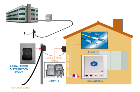
Cable modem and xDSL helped residential broadband get off the ground. Now, however, the sheer speed of fiber overcomes bandwidth limitations of coax and copper. To illustrate, rising consumer demand for big-screen LCD displays can chew up 19 Mbps of bandwidth per channel. In addition, broadband connections are constantly clamoring for more band-width, both upstream and downstream. With busier lives, families want high-speed broad-band communications to transfer e-mail, digital photos and Internet files and they also want entertainment options such as time-sensitive, interactive video gaming that requires bi-directional bandwidth capability. With the typical household having three or more TVs and the ferocious appetite of broadband vying for capacity, it is easy to see that an abundant supply of fiber bandwidth must be included in the design and construction of the development. Figure 1 shows the basic FTTH architecture.
Reliable Capacity
Noisy channel conditions, inclement weather, environmental clutter such as buildings and trees, corroded connections and distance limitations can all impact the reliable delivery of residential broadband. However, the FTTH network access architecture is immune to all of these conditions so there is virtually no downtime. In addition, economical battery backup at the residential NID automatically kicks in when line power is interrupted. Furthermore, FTTH assures the demanding subscriber that they always receive the high-speed broadband capacity that they are paying for, both upstream and downstream, no matter how loaded the access network may be. This built-in reliability is no longer the exception but rather what the homeowner now expects and the builder’s life becomes much easier with satisfied homeowners.
Easy Deployment
Making the optical channel ready for signals once required a skilled technician to carefully splice fiber cables together. Today, the success of FTTH is no longer tied to fiber splicing in the field. As already alluded to, the distribution and drop segments of the FTTH network are easily deployed and intuitively connected. For example, the preterminated fiber drop can reduce subscriber connection time by up to 50 percent because it can be easily screwed into the terminal and the NID by an installer who does not need to know anything about fiber. In the distribution segment, the ease of deployment can shave off 80 percent of the deployment time, because once the terminal distribution system has been placed, homes are immediately ready to be connected into the network.
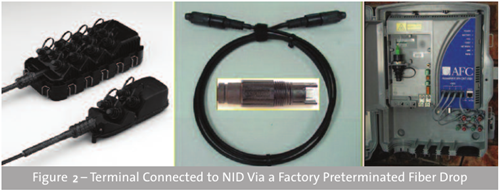
In addition, with FTTH, there is no need for high-voltage power supplies in the neighborhood. Manufacturers are also continuing to improve the appearance and reduce the size of fiber cabinets and terminals relative to the traditional copper products. Combined, this results in a much more aesthetically pleasing deployment than ever before.
Future Proofing
An FTTH network offers land developers an enviable return on their investment capital. Timely planning today can net thousands of dollars in profit. For example, if you invest $500 per home to deploy the fiber jumper and connecting hardware and the home then sells for $5,000 more than it would have otherwise, your investment just returned a handsome 1000 percent profit. That is easy math and easy money.
The return on fiber investment does not stop with its deployment, however. The network operator will also appreciate that robust, reliable and cost-effective FTTH network as they seriously consider their operational expenses. For example, an optical access network featuring segments that can, by design, be quickly connected together not only reduces the upfront deployment cost but also will reduce the amount of time required to turn up subscribers, test and troubleshoot the network. As the triple-play battle for the residential customer continues, a preterminated FTTH network can make the business case very enticing because it sets the network operator’s stage for reduced operational costs and additional revenue from advanced services such as home security and home networking.
Operationally, fiber drop cables are quickly and easily screwed into terminals and residential network interface devices (NID) across the country to save both time and money. Without these key advances in FTTH technology that reduce capital and operational costs, FTTH would continue to wrestle its competitors but now FTTH wins the access investment hands down.
Beneficial Solution
Modern day residential services like HDTV and high-speed broadband that enhance the quality of life in homes are being delivered via FTTH. Looking forward, FTTH residential developments ensure that advanced services such as telecommuting, telemedicine and distance learning will all be transparently realized. FTTH results in reduced commutes and environmental pollution, prolonged quality of life, and education, education, education. Broadband communications is a key element in an increasingly competitive global economy. With FTTH, the world will be better positioned for social and economic prosperity.
Summary
To sum up, FTTH deployment is unstoppable with all the positive impacts that fiber affords. If you are still waiting for service providers to install cable and manually turn up services, then you are left behind.
Posted by: angelina at
02:23 AM
| No Comments
| Add Comment
Post contains 913 words, total size 7 kb.
May 20, 2016
Ethernet as the networking standards, enables computers to locally connect to each other, which is the ultra-strong backbone to the many networks we use every day. Although most of the Ethernet market is still running around 1 Gbqs or 10 Gbqs, there is a strong interest in higher data rates. Many hardware vendors like Cisco, Finisar, Huawei and Brocade have recently announced support for 100 Gigabit Ethernet and telecom vendors around the world have also shown interest in launching 100G networks. All these events shows the sign of the advent of 100 Gigabit Ethernet in the commercial segment. However, is it necessary to move to 100G now? Or should the 100g migration be a smooth one just as the IEEE has made when moving to 40G? This article will highlight the reasons and solutions of upgrading to 100G.
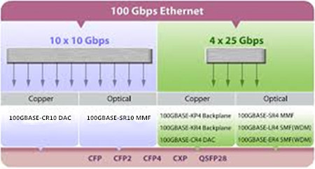
Why Move to 100G?
- Most enterprises today are encouraging telecommuting and promote real-time, high-definition, high-quality voice and video solutions. All these require a huge bandwidth capacity. Additionally, 100G implementations offer an effective means to operate seamlessly within an existing 10G network infrastructure, avoid the need for additional optical amplifiers, dispersion compensators or regenerators. 100G is today’s choice to scale networks in a way that delivers the required capacity in the most efficient manner, readying the network for tomorrow’s bandwidth crunch.
- Another interesting point is the efficiency of 100G Ethernet compared to link aggregation that is used today. As of now, a 10 x 10G Ethernet link aggregation can not give a throughput of up to 100 Gbps. This limitation can be overcome with a true 100G connection which can give a 100Gbps bandwidth, thus allowing high capacity links to scale even further. Considering all these, if not this year or the next, 100G will be widely adopted soon.
- Last but not the least, the industry have come together in order to create a healthy 100G ecosystem, which will be beneficial for the entire community. This broad inclusion will result in a fast introduction of 100G solutions that will meet industry performance, size, cost, and power requirements. If the cost drive is right, once 100G is standardized and commercially available, network operators will quickly capitalize 40G investments and adopt 100G transmission for their future deployments.
Migrate to 100G with 100G Transceiver Modules
There are several form factors for supporting 100GbE including CFP, CFP2, CFP4, QSFP28 and CPAK. The following will make a clear introduction to all of them.
CFP Transceiver
The CFP is the very first 100G transceiver for the transmission of high-speed digital signals, the C stands for the Latin letter centum (means 100). The CFP module was designed after the SFP interface, but is significantly larger to support 100 Gbqs using 10 x 10 Gbit/s lanes in each direction (RX, TX). The optical connection can support both 10 x 10 Gbit/s and 4 x 25 Gbit/s variants of 100 Gbit/s interconnects. There are four common types of CFP transceiver modules, such as 100GBASE-SR10 in 100 meter MMF, 100GBASE-LR10 and 100GBASE-LR4 in 10 km SMF reach, and 100GBASE-ER10 and 100GBASE-ER4 in 40 km SMF reach respectively.
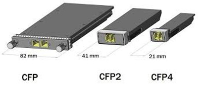
As improvements in technology have allowed higher performance and higher density, which drives the development of the CFP2 and CFP4 specifications. While CFP, CFP2 and CFP4 are electrical similar, they specify a form-factor of 1/2 and 1/4 respectively in size of the original specification. Note that CFP, CFP2 and CFP4 modules are not interchangeable, but would be inter-operable at the optical interface with appropriate connectors.
QSFP28 Transceiver
QSFP28 is the same footprint as the 40G QSFP+ module. Just as the 40G QSFP+ module is using four 10Gbps lanes, the 100G QSFP28 is implemented with four 25Gbps lanes. In all QSFP versions, both the electrical lanes and the optical lanes operate at the same speed, eliminating the costly gearbox found in CFP, CFP2, and the CPAK. The QSFP28 module has an upgraded electrical interface to support signaling up to 28Gbps signals, yet keeps all of the physical dimensions of its predecessor. As QSFP28 technology becomes even maturer, QSFP28 transceivers will become more and more popular in 100G optics market. The above image shows a QSFP-100G-SR4-S. it is Cisco 100GBASE-SR4 QSFP28 transceiver module.
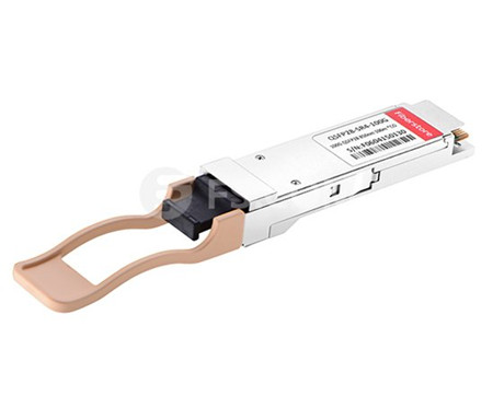
100GBASE-SR4 QSFP28 transceiver and 100GBASE-LR4 QSFP28 transceiver are the two main types of the QSFP28 transceivers. The former is specified to operate over multimode fiber (MMF) with the maximum link length of 70m on OM3 and 100m on OM4, while 100GBASE-LR4 QSFP28 is standardized to work through single-mode fiber (SMF), able to realize 10km link length.
QSFP28 vs. CFP
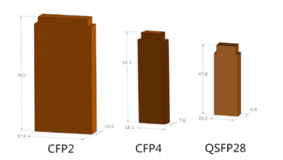
QSFP28 and CFP are the two common 100G optical transceivers available on the market. As noted before, CFP is the first-generation 100G transceiver. It is the common scene that QSFP28 makes an appearance and CFP takes a bow, which reflects the trend in the industry to aggressively bring 100GE density up and costs down. CFP4 is half the width of CFP2, which is half again the width of CFP. QSFP28 has the same footprint and faceplate density as QSFP+ and is just slightly smaller than CFP4. Theoretically, QSFP28 seems to have the density advantage over CFP4, but CFP4’s higher maximum power consumption gives it the advantage on longer reach optical distances. However, the CFP is much more expensive than QSFP28 and will not be used for lower speeds because of the high cost.
CPAK Transceiver
CPAK is another newcomer to supporting 100G network. This is a proprietary form factor from Cisco but the interfaces demonstrated are IEEE standards and will interoperate with the same interfaces supported by other form-factors. Together, these solutions will deliver the smallest form-factor, most efficient 100-Gbps optical transceiver portfolio in the industry. Cisco CPAK will be available in several IEEE-standard optical interfaces.
Conclusion
Within the next several years, 100G is doom to become the dominant backbone technology in terms of its high capacity over 10G and surpassing would-be high-speed contender 40G. Of course, we must count on the components and systems suppliers to build products that meet technical and economic requirements while allowing a smooth migration to the 100G infrastructure that is being put in operation today.
Posted by: angelina at
03:38 AM
| No Comments
| Add Comment
Post contains 1022 words, total size 8 kb.
May 18, 2016
The virtualized workloads, cloud applications, and big data services today are driving previously server and data center fabric to an unimagined level. The existing 1Gbqs or 10Gbqs are gradually overwhelmed by higher-bandwidth like 40Gbps or 100Gbqs. Thus high-capacity optical technology and cabling infrastructure are required to support those servers and applications for 40Gbps upgrading. However, it might be too costly to replace all your equipment for 40G transition. So this article will introduce a cost-saving solution to help you smoothly migrate to 40GbE with the use of 40G BiDi QSFP+ transceiver.
40G BiDi QSFP Transceiver Overview
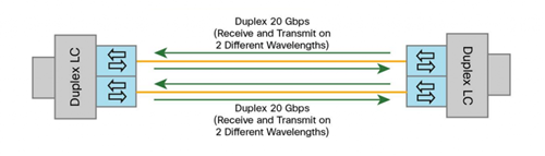
Bidirectional optical transceivers used for 40GBASE-SR-BD have the same 10-Gbps electrical lanes, which are then combined in the optical outputs, requiring two fibers with an LC connector interface. Each fiber simultaneously transmits and receives 20Gbps traffic at two different wavelengths. Figure 1 shows a electrical and optical lanes diagram of bidirectional optical transceiver. It can support link lengths of 100 meters and 150 meters, but on duplex LC OM3 and OM4 multimode fibers, which enables it use the existing 10 gigabit duplex MMF infrastructure for migration to 40 Gigabit Ethernet connectivity. Take QSFP-40G-SR-BD as an example, the Cisco QSFP 40Gbps BiDi transceiver supports link lengths of 100 and 150 meters on laser-optimized OM3 and OM4 multimode fibers, respectively. And this transceiver can also support 30m over OM2.
Difference Between 40GBASE-SR4 Parallel and Bidirectional Optical Transceivers
The IEEE standard 802.3ba released several 40Gbps based solutions, including 40GBASE-SR4 parallel optics solution for multimode fiber (MMF) and bidirectional 40Gbps transceiver. Unlike 40G BiDi QSFP transceiver, 40GBASE-SR4 parallel transceiver is simultaneously transmitted and received over multiple fibers. This transceiver has 10Gbps electrical lanes that are mirrored in the optical outputs and thus require eight fibers with an MTP connector interface. Each fiber either transmits (Tx) or receives (Rx) 10-Gbps traffic at a single wavelength.
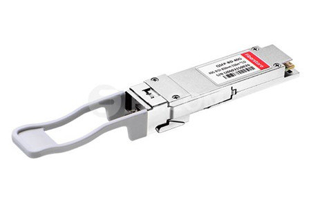
While 40GBASE-SR Bi-Directional QSFP (see in Figure 2) has two 20Gbps lanes at two different wavelengths over a single MMF strand, enabling an aggregated 40Gbps link over a two-strand multimode fiber connection. It can support link lengths of 100 meters and 150 meters, but on duplex LC OM3 and OM4 multimode fibers, which enables it use the existing 10 gigabit duplex MMF infrastructure for migration to 40 Gigabit Ethernet connectivity.
To sum up, this two-fiber 40Gbps Bidirectional (BiDi) multimode solution uses two different transmission windows (850 nm and 900 nm) that are transmitted bidirectionally over the same fiber, which will allow the use of same cabling infrastructure for 40 Gigabit Ethernet as was used for 1 and 10G Ethernet application. While the parallel multimode optical transceiver operates at a wavelength of 850nm. Additionally, the connector type was converted from the traditional 2-fiber LC duplex connector to a 12-fiber MTP connector.
Use Your Existing 10 Gigabit Ethernet Fiber for 40 Gigabit Ethernet
Whether your cable plant is structured or unstructured, 40G BiDi QSFP transceiver delivers significant savings and a smooth migration to 40 Gigabit Ethernet. For instance, in a structured cabling system, devices are connected directly with fiber cables within short distances in a data center network. The existing 10Gbps direct connections commonly use LC MMF fiber, 40GBASE-SR Bi-Directional QSFP therefore allows cable reuse, resulting in zero-cost cabling migration from direct 10Gbps connections to direct 40Gbps connections. It is the same case with the structured cabling system. Figure 3 shows 40Gbps structured cabling solutions with 40GBASE-SR Bi-Directional QSFP transceivers and the similar 10Gbqs structured cabling with 10GBASE-SR SFP+.
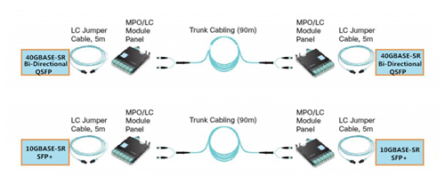
The BiDi transceiver enables the use of an existing 10 Gigabit Ethernet fiber plant infrastructure for 40 Gigabit Ethernet, delivering four times the bandwidth over the same fiber plant and up to 70% savings over other current solutions. QSFP 40 Gigabit Ethernet BiDi technology removes 40Gbps cabling cost barriers for migration from 10Gbps to 40Gbps connectivity in data center networks. It provides simpler and less expensive 40Gbps connectivity compared to other 40Gbps transceiver solutions. The Cisco QSFP BiDi transceiver allows organizations to migrate their existing 10Gbps cabling infrastructure to 40Gbps with little capital investment.
Conclusion
For building out new data centers, deploying 40 Gigabit Ethernet for aggregation and core is no longer an option but a requirement to meet today’s data demands. Designing your new fiber cable plant with 40 Gigabit Ethernet BiDi transceiver allows you to reduce your fiber requirements while future proofing your data center for 100 Gigabit Ethernet.
Posted by: angelina at
02:57 AM
| No Comments
| Add Comment
Post contains 728 words, total size 6 kb.
May 12, 2016
SFP optical transceiver is generally regarded as the most useful technological advancements of the telecom industry. This transceiver is less than half the width of the GBICs and created under the Multi-Source Agreement (MSA). SFP transceiver is hot-swappable, which is highly beneficial to network designers. What’s more, the smaller size and high performance enable the enterprises to cost-effectively migrate to Gigabit Ethernet. There are a number of small form pluggable (SFP) optical modules and network accessories to select from. Therefore, to save your troubles, this article elaborates three basic information of SFP transceiver module to make sure you have chosen the right one.
The Origin of SFP Optical Module
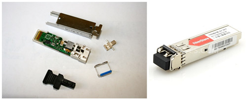
SFP transceiver modules are hot-pluggable module with LC interfaces. SFP can be simply treated as the upgrade version of GBIC. SFP module volume ratio reduced by half, the same panel can be configured in more than double of ports. Other features of SFP Module are generally the same as the GBIC. Devices like NETGEAR AGM731F SFP (see in Figure 1) Modules tend to be smaller and are only about half the size of GBIC optics. AGM731F is 1000BASE-SX SFP that operates over the inexpensive 850nm wavelength for a distance of 550m. The SFP module sends speeds that range from 100 Mbps to about 5 Gbps. Their transmission length begins at about 500 meters and goes up to 120 kilometers.
Types of SFP Optical Transceiver
SFP transceivers are capable of providing an exceptional amount of variation to consumers. Typically, optical transceivers come in either multimode fiber or single-mode fiber type. And according to different standard, the SFP module is commonly offered in four different categories, which include SX, LX, ZX, and DWDM. Each of these different types interface with copper cables and this permits the motherboard to communicate with the unshielded twisted pair (UTP). CWDM cables and single-mode bi-directional fiber optic cables will transmit data both upstream and downstream.
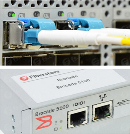
SFP optical transceivers are available in wavelength of 850nm/1310nm/1550nm/1490nm/1530nm/1610nm. Of which the 850nm wavelength is SFP multimode with a limited transmission distance within 2km. While the 1310/1550nm is SFP single-mode, and the transmission distance is longer than 2km. The price of the 850nm/1310nm/1550nm SFP transceiver module is relatively cheaper than the other three. Take E1MG-LX-OM as an example, it is Brocade 1000BASE-LX SFP operating at a wavelength of 1310nm. E1MG-LX-OM can support a link length of 10km. The above image presents a Brocade E1MG-LX-OM with a single-mode fiber inserting into a Brocade Switch.
Features of the SFP Optical Transceiver
- MSA Standard-based Design Assures Compatibility
An SFP transceiver is capable of transferring rates up to 4.25 Gpbs. The MSA standard-based design assures compatibility. XFP form factor is similar to the SFP type. The functionality increases about three times at 10 Gpbs with this type of transceiver type.
- Digital Diagnostics Monitoring (DDM) Enhances Management Capability
Digital optical monitoring (DOM) enables a real time link to be established between the switch and the SFP transceiver. Thus network designers have the ability to monitor real-time parameters such as optical inputs and output power, laser bias, and supply voltage, etc. Additional, the DOM functionality enables the capability to implement digital alarms and warming.
- Hot-swappable Design Facilitates Network Maintenance
SFP transceivers are hot-swappable and have the capability to allow design modification until the final stages of manufacturing. This makes it easier to accommodate different connector interfaces.
Last but not least, an SFP cage may be required for proper operation of the device. It’s usually mounted to the PCB board and will accept the transceiver. It eliminates extra manufacturing steps and reduces costs. SFP transceivers also have a higher optical reliability and will permit higher soldering temperatures. SFP transceivers are recommended by fiber optic component providers to ensure proper data transmission.
Conclusion
SFP transceivers are expected to perform at data speeds of up to 5 Gbps, and possibly higher. Because SFP modules can be easily interchanged, the fiber optic networks can be upgraded and maintained more conveniently than has been the case with traditional soldered-in modules.
Posted by: angelina at
02:15 AM
| No Comments
| Add Comment
Post contains 673 words, total size 6 kb.
May 10, 2016
Evolution is taking placing every minute in the data center in order to better meet people’s needs, and one of the main changes in the data center is that data center designers want to migrate to 40G or 100G without replacing the existing multimode cabling infrastructure. It is known that every data center requires optical transceivers and Direct Attach Cable (DAC) for interconnect. Recently many vendors supply 40G optical devices including QSFP+ optical transceivers, QSFP+ DAC cables and QSFP+ AOC cables. The QSFP+ DAC cables from Cisco and Juniper are highly favored by overall users. Thus in today’s article, we will pay more attention to the illustration of the 40G QSFP+ DAC cables, especially the Juniper QFX-QSFP-DAC-3M and Cisco QSFP-H40G-CU3M.
40G QSFP+ to QSFP+ Direct Attach Copper Cable
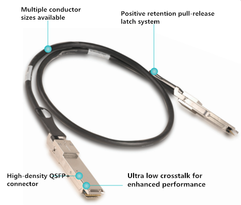
QSFP+ to QSFP+ direct attach copper cable offers a highly cost-effective way to establish a 40G link between QSFP+ ports of QSFP+ switches within racks and across adjacent racks, which is very suitable for very short distances application. These cables connect to a 40G QSFP port of a switch on one end and to another 40G QSFP port of a switch on the other end. Supporting similar applications to SFP+, these four-lane high speed interconnects were designed for high density applications at 10Gb/s transmission speeds per lane. One QSFP+ to QSFP+ direct attach copper cable link is equivalent to 4 SFP+ cable links, providing greater density and reduced system cost. The following image presents an inner structure of QSFP+ DAC cables.
There are two QSFP+ DAC cables available on the market—Passive and active QSFP+ to QSFP+ direct attach copper cables. With an active QSFP+ to QSFP+ direct attach copper cable assembly, the connection is capable of distances of up to 10 meters, while with a passive QSFP+ to QSFP+ DAC cable assembly, the connection is capable of distance of up to 7 m. QSFP+ passive DAC cables are hot-removable and hot-insertable. This cables use integrated duplex serial data links for bidirectional communication and are designed for data rates up to 40 Gbps. Passive DAC cables have no signal amplification built into the cable assembly. The following part will illustrate two passive QSFP+ DAC cables—QFX-QSFP-DAC-3M and QSFP-H40G-CU3M.
- QFX-QSFP-DAC-3M
This Juniper quad small form-factor pluggable plus (QSFP+) DAC cables are suitable for in-rack connections between two QSFP+ ports. It is suitable for short distances of up to 3 m, making itself ideal for highly cost-effective networking connectivity within a rack and between adjacent racks.
- QSFP-H40G-CU3M
This is also a QSFP+ DAC cable just like QFX-QSFP-DAC-3M, but it is from Cisco. As the name implies, it can support a link distance of up to 3 m. Cisco QSFP to QSFP copper direct-attach cables are suitable for very short distances and offer a very cost-effective way to establish a 40GbE link between QSFP ports of Cisco switches within racks and across adjacent racks. To sum up, these two QSFP+ cables have the same performance but used on different Switch brand. Next, a short description about how to use QSFP+ DAC cables will be shown to you.
How to Use a 40G QSFP+ Direct Attach Copper Cable
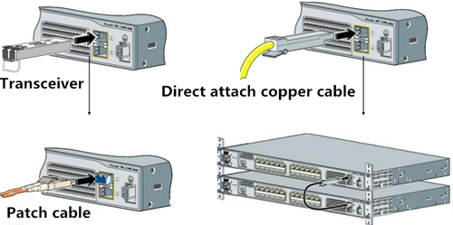
As we known, QSFP+ DAC cables can be mainly divided into two types. One is QSFP+ to 4 SFP+ direct attach breakout copper cable, and the other is QSFP+ to QSFP+ direct attach copper cable. In fact, there is a third type called QSFP+ to 4 XFP breakout cable. However, regardless of what type of cables, they are both used to connect switch to switch or switch to sever. For a QSFP+ to 4 SFP+ direct attach breakout copper cable, it has a QSFP+ connector on one end and four SFP+ connectors on the other end. In terms of a QSFP+ to QSFP+ direct attach copper cable, it has a QSFP+ connector on both ends of the cable. When we use a fiber optic transceiver and patch cable to establish a fiber link, we should firstly plug the transceiver to the switch and then plug the patch cable to the transceiver (see in Figure 2). But for a QSFP+ direct attach copper cable, either SFP+ connector or QSFP+ connector, can be both directly inserted into the switch and don’t need a transceiver at all, which provides a really cost-effective solution for interconnecting high speed 40G switches to existing 10G equipment or 40G switches to 40G switches.
Summary
There are many other vendors offering QSFP+ DAC cables. I can’t list all of them here for you to choose from. Cisco and Juniper QSFP+ DAC cables, as a representative of the QSFP+ DAC cables have been introduced in this article. Just remember that DAC cables must be compatible with the Switches of the network. In fact, the Switch market has been monopolized by large vendors like Cisco, Juniper and HP. And all the original optical transceivers from them are also very expensive. Therefore people are turning to purchase from OEM vendors for the competitive price and high performance. If you are thinking about upgrading to 40G network, QSFP+ DAC cables like QFX-QSFP-DAC-3M and QSFP-H40G-CU3M are indispensable.
Posted by: angelina at
02:25 AM
| No Comments
| Add Comment
Post contains 852 words, total size 6 kb.
May 05, 2016
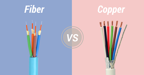
There is no denying that people may encounter a dilemma when accessing which type of network cable (fiber or copper) to install, and which type you should go with. As technology develops further and supporting devices catch up, fiber optic technology is becoming more and more popular. As we know, the most obvious difference between the fiber optic network and copper network is the speed of transmitting data. Associate Professor Robert Malaney has said, "When we are talking about 'speed', we were actually talking about throughput (or capacity)—the amount of data you can transfer per unit time.†Of course, fiber optic cable can definitely transfer more data at higher speed over longer distances than copper cable. So here comes the question: why is the fiber optic technology better than copper?
How Do They Work?
To solve this problem, first we should get down to the working principles of them. Copper network works by sending electrical pulses through a copper wire. The power of the signal dictates how much of it will be retained by the time it reaches its destination. At the destination (e.g. the router), the wire’s electromagnetic field is constantly monitored for changes. As the field gets stronger, the destination registers a "1.†If it dips below a certain measurement, a "0†is registered. Copper cables must have several wires built in to accommodate the mechanisms that allow Ethernet routers to properly process signals. While fiber patch cables transmit data by sending pulses of light generated by a light emitting diode or laser along optical fibers. It conserves the data being sent by not allowing light to stop around the middle, which can be highly beneficial when you’re trying to transfer data over long distances.
Why Fiber Optic Transmission Is Faster?
It is the common sense that fiber can transmit faster data rate than copper. Why is that? Because copper has a significant signal-loss issue. To read a signal correctly during operation, you have to know the exact moment the signal has stopped and the exact moment it began. As a signal is forced to travel farther, the difference between a start and a stop (zero and one) gets very fuzzy. Copper is best used for maintaining a continuous electrical current for the great conductive property. However, for signaling, it remains a very poor material. It’s still good for local networks, but not necessarily something we should be using for global communication infrastructure, considering that Cat6a copper cables can lose 94 percent of their signal at 100 meters distance. Researchers have recently been able to send data at 10 Gbps through copper, but at distances no larger than 30 meters.
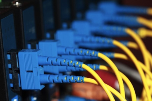
Fiber, on the other hand, can theoretically send terabytes per second of data without so much as a 3% data loss over 100 meters. The signal retention and signal clarity are two things playing an important role here. Not only do you absolutely know when the signal began and ended, but you receive a very strong signal across the wire. This allows communication at dizzying speeds so fast that most routing technologies still can’t process them fast enough. Figure 2 shows a single-mode fiber cable installation.
Through the signal’s lifecycle, fiber does another very important thing: It protects the signal from any electromagnetic interference. EM fields can influence how copper transfers data, but since optical fiber is made of extruded silica, it’s magnetically neutral. If you would have a perfect cable (there’s no such thing yet), you could theoretically send a signal across the United States without making any stops along the way.
Superiority of the Fiber Optic Cable
In both cases you're detecting changes in energy, and that's how you encode data. With copper wires you're looking at changes in the electromagnetic field, the intensity of that field and perhaps the phase of the wave being sent down a wire. With fiber optics, a transmitter converts electronic information into pulses of light—a pulse equates to a one, while no pulse is zero. When the signal reaches the other end, an optical receiver converts the light signal back into electronic information. The following table concludes the reasons why we should choose fiber.
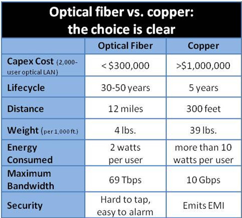
The throughput of the data is determined by the frequency range that a cable will carry. Generally, the higher the frequency range, the greater the bandwidth and the more data that can be put through per unit time. So here we can get the key point: fiber optic cables have much higher bandwidths than copper cables. This difference determines that fiber optic cable can transfer a large sum of data at a very high speed, while the copper cable would attenuate or lose signal strength at higher frequencies. What is more, fiber optic technology is far less susceptible to noise and electromagnetic interference than electricity along a copper cable. For example, when we want to transmit data over 200 kilometers, fiber optic cable can make it perfectly, while the copper cable would suffer a lot of degradation over that distance.
Last but not the least, an added benefit of fiber optic cables is that they are not a fire hazard. This can also be attributed to the same reason that the cables do not produce EMI—there is no electric current traveling through the core. Fiber optic cables do not break as easily, even though the fiber is made of glass, copper wires are more prone to damage than fiber optic cables are.
Summary
Because of its incomparable superiority, fiber patch cable make itself a more enticing cable infrastructure solution than its copper counterpart. It has been utilized in many new cabling installations and upgrades, such as medical examinations, government services, improved productivity, telecommuting, three-dimensional conferencing and working from home. Copper, however, no longer represents a worthwhile investment and should be retired.
Posted by: angelina at
02:17 AM
| No Comments
| Add Comment
Post contains 974 words, total size 7 kb.
April 29, 2016
The rapid growth in storage and computing services is driving an expansion in both the physical size and overall computing power of the modern data center. This high-speed data interconnects linking the individual optical elements within a data center are typically comprised of fiber optical solutions (multimode or single-mode). Limited to short linking distances, multimode fiber interconnects are most often used to provide server-to-server or server-to-network switch connections within the same rack or chassis. Inter-rack and inter-chassis connections, which usually require greater reach and higher bandwidth, demand a single-mode fiber optic solution and are enabled by WDM-based parallel optical transceivers. Data rates of 10 Gbqs and higher are now commonplace in the modern data center, here is what you should know about data center cabling solution.
Multimode vs. Single-mode Fiber Solution
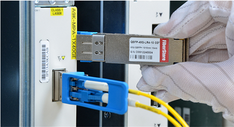
Data rates and link distance are the two important parameters typically characterized for fiber optic interconnect. When considering both of these requirements for a given application, link distance plays a key role in determining what type of optical module or fiber infrastructure to deploy. Applications with individual channel rates of 10 Gbqs requiring link distances of less than 300 m have traditionally been serviced by Vertical Cavity Surface Emitting Laser (VCSEL) based solutions operating over multimode fiber. These applications are often referred to as "Short Reach†by industry standards. For example, the 40GBASE-SR4 of the IEEE 802.3ba physical layer standard defines a 4-lane parallel optical interconnect for operation up to 100 meters in length over OM3 multimode fiber. Take Cisco QSFP-40G-SR4 as an example, this Cisco 40GBASE-SR4 transceiver (see in Figure 1) can support a link distance of up to 150m. Under this standard, 40Gbqs switch-to-switch uplinks can be realized using QSFP+ optical transceivers and MTP connector-based parallel multimode fiber cables. Besides 40GBASE-SR optics, 40G QSFP+ cables (AOC or DAC) are also a practical 40G solution. QSFP+ to 4SFP+ Passive Copper Cable (e.g.HP JG330A) provides a cost-effective solution for 40G short-reach interconnect application.
So called "Long Reach†applications typically involve link distances on the order of kilometers, and rely on more costly Fabry-Perot (FP) or Distributed Feedback (DFB) laser-based solutions running over single-mode fiber. While single-mode solutions provide a greater maximum link distance, they typically do so with higher power dissipation, and as mentioned previously, a higher module cost. Historically, multimode solutions could comfortably satisfy the switch-to-switch interconnect demand within the data center since link distances greater than 300 m were rarely, if ever, required. Now, with the rise of the Mega Data Center comes the realization that maximum switch-to-switch spacing may actually exceed 300 meters, and that a longer reach multimode solution is needed.
Short Reach With Multimode Fiber
Multimode fiber (MMF) has become widely used for up to 10Gbqs. It provides the lowest cost and lowest power connectivity with trouble-free installation for the data center designers. But MMF is running out of bandwidth at 10G, so parallel optics at 40G uses 4x10G channels and uses 10x10G channels for 100G, which has a great impact on the fiber count needed to support equipment. MM links at 10G are also power limited due to the bandwidth penalty caused by the limited modal bandwidth of the multimode fiber. MM links may only have ~<2dB loss budgets meaning that the data center cable cannot have many interconnections especially with the MPO multifiber array connectors which are inherently higher loss than single fiber ceramic-ferrule connectors like LCs and SCs.
Thus parallel optics assemblies use the MPO connector which has 12 or 24 fibers per connector. The limitation of parallel optics with MPO connections includes the masses of fibers required and the fewer interconnects allowable because of the typically higher loss of the MPO connector. Here is an example of a 40G and 100G solutions on multimode fiber. 40G uses a 12 fiber MPO with 4 channels each at 10G for transmit and receive on separate fibers, so there are 4 transmit and 4 receive fibers. Since the MPO connector has 12 fibers, the center 4 are unused just as shown in Figure 2.
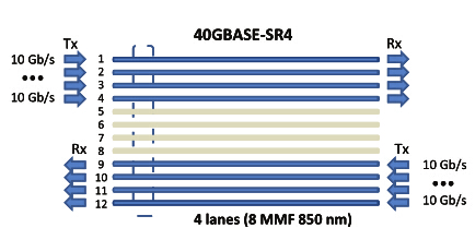
100G uses 10 channels each at 10G for transmit and receive on separate fibers on a 24 pin connector, so there are 10 transmit and 10 receive fibers. Since the MPO connector has 12 fibers in each row, the center 4 are unused. There is another version of 100G being developed that uses 4 X 25g channels which will have shorter reach. This design should use a connection scheme like 40G on a 12 fiber connector.
To sum up, multimode transceivers use inexpensive 850nm VCSELs so the transceivers are cheaper than singlemode but the fiber optic cable plant uses many multimode fibers so the cable plant is more expensive.
Longer Reach with Single-mode Fiber
Single-mode fiber are more preferable for unlimited bandwidth and distance capability when used in data centers. Unlike the parallel 10G channels used with MM fiber, single-mode uses wavelength division multiplexing (WDM) to transmit multiple channels over one fiber at different wavelengths. Thus 40G uses 4X10G wavelengths and 100G is achieved using 4x25G wavelengths. CWDM transceivers cost more than parallel MM transceivers at the current time, but the cabling cost is much lower and expected higher quantity usage will drive costs down. Look what 100million users did for the lasers and CWDM used in fiber to the home (FTTH.)
Conclusion
The rapid expansion of telecommunications networks, and data services, measured either by data volume or bandwidth, means fiber optic technology will be a significant part of future systems. Compared to multimode cabling solutions, single-mode technology is more flexible, lower power and higher bandwidth but more costly.
Posted by: angelina at
07:55 AM
| No Comments
| Add Comment
Post contains 936 words, total size 7 kb.
April 27, 2016
In optical communication networks, there are many devices fundamental to performing smooth technical operation. One indispensable system is called optical transceiver module. A transceiver combines a transmitter and receiver to form a unit and uses the same channels. Optical transceivers are typically found in various form factors, including SFP, GBIC, SFP, XFP and X2 etc, which are often used for computer networking purposes.
Whenever you need to deploy an optical network, you immediately come to think of Ethernet standards and relevant devices. Well, the fact is, some types of Ethernet networks require the utilization of specific types of transceivers. What’s more, you need to balance the budget and your network requirement. For instance, if you are looking for 10G XFP transceivers, you must know about something to get transceivers at very reasonable rates prior to making your decision. The following article will provide some suggestions to help you select the most suitable optical devices for your infrastructure.
XFP Transceiver—Definition & Classification
With the progress and advancement in technology, more and more equipment with latest techniques are being introduced every day. The XFP transceiver is a hot pluggable component intended for 10G system applications. XFP transceiver is also a protocol autonomous optical translation device utilized in various applications such as 10Gbps SDH/SONET, DWDM fiber optic networks and related applications. The XFP transceivers satisfy the relation to MSA launched by various popular companies on the market today. There are numerous XFP transceivers available on the market, including 10GBASE-ZR XFP, 10GBASE-ER XFP, 10GBASE-LR XFP, and 10GBASE-SR XFP. The most widely used is 10GBASE-SR XFP which has a working distance of 300 meters maximum via OM3 MMF.
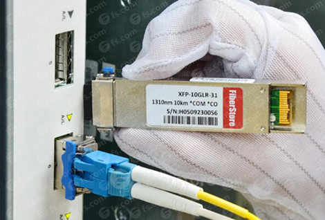
The other types of XFP function with SMF:
- The maximum distance of 10GBASE-LR XFP is 10 kilometers via 1310nm SMF;
- The maximum distance of 10GBASE-ER XFP is 40 kilometers via 1550nm SMF;
- The utmost distance of 10GBASE-ZR XFP is 80 kilometers via SMF.
10GBASE-LR XFP is widely utilized in telecom field, take XFP-10GLR-OC192SR as an example. This Cisco compatible 10GBASE-LR XFP can support a distance of 10km over single-mode fiber. Juniper XFP-10G-L-OC192-SR1 possesses the same function with the XFP-10GLR-OC192SR, but they are offered by different vendors.
Select the Most Suitable Optical Transceivers
After the certification of X2 transceivers and XENPAK, this XFP transceiver is the new invention for 10G solution. Various vendors are available in providing 10G XFP transceivers. You can purchase these transceivers from a local store or over the website. Since many companies have their personal website where people can purchase at home, but the most challenging part is to find a reliable vendor that provides top quality products at affordable price. To simplify your process, two most widely used and reliable brands of transceivers are Cisco and Juniper, just as I have listed above. Just make sure you perform some reading on the web for reviews and advice from people who have used these brands, which will help you create a more informed purchase decision and cut down your cost.
However, the Cisco or Juniper XFPs are too expensive. People can not afford the high cost. Thus many designers are turning to compatible ones which have the same functions and ideal compatibility with the original brand like Cisco, Juniper, Finisar, etc. These 3-rd party XFP transceivers are also developed on the basis of international industrial standards and are severely checked for compatibility with tools and devices from large organizations in industry. The compatible XFP transceivers are extremely cost-effective with only one tenth of original price! That’s why they are more popular than the original ones.
Posted by: angelina at
02:16 AM
| No Comments
| Add Comment
Post contains 597 words, total size 5 kb.
April 22, 2016
Recently, enterprises are replying more and more on the cloud-based application, storage and management system for both internal use and remote access. If network infrastructure still uses 1000BASE-T network and SFP on the back-end today, it obviously can not meet people’s requirement and will be left behind by its competitor. The most cost-effective solution is to scale their network up by using 10 Gigabit Ethernet SFP+ equipped devices at the top pf the rack. Of which 10G SFP+ passive direct attach copper (DAC) cables are indispensable and highly recommended for short-reach interconnect application. Cisco, as the telecom giant, offers a wide selection of SFP+ passive copper cables in length raging form 0.5m all the way to 5m. The following article will go on to the detailed information about Cisco 10G SFP+ passive copper cables.
Introduction to Cisco SFP+ Passive Copper Cables
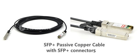
SFP+ copper twinax direct-attach cables from Cisco are developed as a cost-effective alternative for very short links in high-speed interconnect application within racks and across adjacent racks. This SFP+ passive copper cable assembly uses twinax shielded cable with robust die cast connector interfaces for enhanced support of high frequency data rates, which means signals travel over parallel pairs of conductors. 10G SFP+ twinax copper cables contains 2 pairs—one for transmit (Tx) and one for receive (Rx) and each shielded pair is surrounded by an overall shield. Cisco passive twinax cables are offered in different lengths of 1, 1.5, 2, 2.5, 3 and 5 meters. I know you are quite familiar with SFP+ passive copper cable, now let’s get down to the role of the 10G SFP+ passive DAC cables.
What Is the Role of the 10G SFP+ Passive Copper Cable?
10G SFP+ passive copper cable is effectively viewed as a transparent cable to the switch and requires little to no direct power to operate. It seems that a passive cable just acts as a pass-through transmission medium and do nothing to the signal, then how exactly is the signal processed in the first place? In most cases, this activity resides exclusively inside the electronic circuitry of the switch. The switch will generally perform the following functions to the signal prior to its transmission through the cable assembly:
- Signal Conversion
Signal conversion occurs first in instances where electrical circuits must interface with optical circuits. Since some switches operate select ports in the optical domain (i.e. fiber optic light pulses), that optical signal must then be converted over to an electrical signal that can be further modified and reliably sent over an electrical transmission medium such as copper cabling.
- Signal Conditioning
Signal conditioning is in essence preparing the signal for the next step of the process. This could involve formatting the signal using a standardized electrical modulation pattern that other down-stream equipment can recognize. This could be conditioning the signal into a 10-bit/8-bit pattern where 8-bit segments of data require encapsulation in a 10-bit "packet†featuring additional header information that is used for error correction and re-transmission mechanisms.
- Signal Amplification
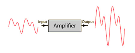
The next critical step, signal amplification, will raise the newly conditioned signal from a low-strength "machine level†signal to a far more powerful or amplified signal. Signals are kept at lower strength levels inside the switch’s processing architecture for several reasons, including reduced power consumption, improved heat dissipation, reduced noise/interference characteristics and so on. However, this internal "baseband†signal is far too weak to travel the typical distances commanded by cable assemblies. Theyâ€re only designed to travel a few inches around a PC-board or chipset!
- Signal Equalization
Now, if we were dealing purely with signals of past eras such as 10/100 Megabit (Fast) Ethernet, the final phase known as signal equalization would be totally unnecessary. However, a signal such as the one sent over SFP+ Cables requires hundreds of MegaHertz (MHz) or even GigaHertz (GHz) of signal bandwidth to operate effectively. The problem with such wide-banded signals is that the lower portion of the signal may arrive at the other end of the cable faster or stronger than the higher portion of the signal. This causes an anomaly known as time delay and/or phase delay SKEW that absolutely wreaks havoc on the signal itself, sometimes to the point of being unrecoverable.
To avoid this, the signal must be equalized accordingly. On the transmission channel of the link, the signal must go through a process called Pre-Emphasis. It does exactly what it sounds like—it pre-emphasizes (boosts) the portion of the signal that tends to get skewed. Similarly, on the receive channel of the link, the signal portion must be reciprocally de-emphasized (lowered). This complete process of equalization equalizes the signal so that it is uniform and free of SKEW and therefore ready to be sent over a specific transmission medium, i.e. a SFP+ passive DAC cable.
Third-party Cisco SFP+ Passive DAC Twinax Cable
Enterprises today are seeking to cut down the costs, but the original Cisco SFP+ passive copper cable are very expensive. Therefore 3rd-party SFP+ optics with its lower price is the ideal choice.
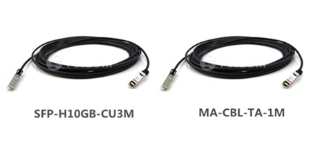
- SFP-H10GB-CU3MSFP-H10GB-CU3M from Fiberstore is a Cisco compatible 10GBase-CU SFP+ to SFP+ direct attach cable that operates over passive copper with a maximum reach of 3.0m. It has been programmed, uniquely serialized, and data-traffic and application tested to ensure it is 100% compliant and functional. Our direct attach cables are built to comply with MSA (Multi-Source Agreement) standards. Our 10G SFP+ passive copper cables are well-tested before shipping worldwide and cost much lower than the original ones.
- MA-CBL-TA-1MMA-CBL-TA-1M from Fiberstore is a Cisco compatible SFP+ to SFP+ direct attach cable that operates over passive copper with a maximum reach of 1.0m. This is a twinax cable featuring two male SFP+ connectors.
Conclusion
Cisco 10G SFP+ passive copper direct attach cable is defined for 10GbE applications over passive copper cable within a very short reach, but its popularity are largely limited by the high cost. Thus people are seeking to purchase from OEM vendors like Fiberstore. All products offered by Fiberstore are tested in-house to ensure that they will arrive in perfect physical and working condition.
Posted by: angelina at
04:09 AM
| No Comments
| Add Comment
Post contains 1015 words, total size 8 kb.
April 20, 2016
SFP is a new generation of optical module transceivers. Featured by the compactness, flexible and economical design and high performance, SFP transceivers soon replace all the existing interface standards in networking after certification. To satisfy some projects, whose telecommunication equipment or networking device needs optical transceiver requirement. For better sharing SFP transceiver modules, this blog is illustrating knowledge of this hot-pluggable transceiver.
Small Form Factor Pluggable (SFP) Definition
The SFP transceiver is specified by Multisource Agreement (MSA), which was developed and followed by different transceiver manufacturers. SFP transceivers have a wide range of detachable interfaces to multimode or single-mode fiber optics, which allows users to select the appropriate transceiver according to the required optical range for the network.
Main Features of SFP Transceiver
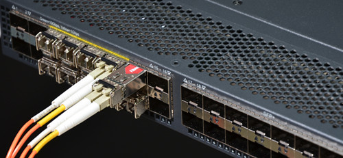
SFP transceiver stands for Small Form-factor Pluggable transceiver. This transceiver is compact and hot-pluggable. It is widely used in the field of Data Communication and Networking. This transceiver mainly acts as an interface between a networking switch and its interconnecting cable as shown in Figure 1. This networking device can be any switch, repeater, router, multiplexer etc. The interconnecting cable may be made of copper or it can be an optical fiber cable. This transceiver which interfaces a device in the network to the cable is highly popular and can support devices and cables of various network vendors.
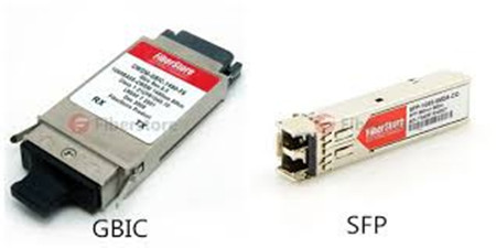
Superseding the GBIC transceiver, SFP modules are also called "mini-GBIC†due to their smaller size. By choosing the appropriate SFP module, the same electrical port on the switch can connect to fibers of different types and different wavelengths. If the fiber is upgraded, the SFP module is replaced.
Optical SFP transceivers come with digital monitoring features with the help of which one can monitor the performance of SFP in real time. This feature can be used to monitor SFP’s performance parameters like working temperature and wavelength, supply voltage, optical input and output etc. These transceivers have a PCB in them which connects to an electrical connector designed for SFP. SFP transceiver also has a 256 byte EEPROM memory. SFP transceivers are housed in a metal enclosure and their power dissipation is low. They operate over a wide temperature range and support a large number of different types of cable. An improved version of SFP standard called SFP+ can support transmission rates up to 10Gbps.
Certain SFP transceivers can also use copper cables as interface. This will cause a device in the network to send their data over shielded or unshielded twisted pair cable. Usually such copper cable interfaces are used when the information to be transmitted needs to cover only shorter distances where use of copper cable is more economical than optic fiber cables.
Types
SFP transceivers are of various types and each type comes with different configurations of transmitter and receiver. It is important to choose a proper transceiver to act as an interface between the device and the cable. This choice of transceiver is usually made based on the type of fiber optic cable. Such SFP transceivers which are used to provide the necessary reach to a fiber optic cable are categorized as optical SFP. These SFP modules are of several versions, wherein each version has different values of working wavelength and working distance: typical wavelength of different modules are 850 nm, 1310 nm and 1550 nm with working distances of 550m (SX), 10 km (LX) and 40 km (XD) respectively. J4858B and E1MG-LX-OM are 1000BASE-SX and 1000BASE-LX SFP, which are greatly welcomed by users. And there are also other types of SFP like DWDM, CWDM and bi-directional SFP with single fiber having upstream and downstream working wavelengths of 1310 nm and 1490 nm.
SFP vs. GIBC
SFP transceivers are compatible with a number of communication standards like Ethernet, SONET along with many other standards. SFP is an upgraded version of Gigabit Interface Converter (GBIC) module. SFP uses LC fiber optic cable for its interface whereas SC cable interfaces are used in GBIC. SFP is more space saving than GBIC, since the former has only half the size of the latter. SFP has transmission rate ranging from 100Mbps to 4Gbps and it can work at distances ranging between 500 meters to hundreds of kilometers. The ‘hot-pluggable’ feature of SFP makes it flexible. Any future changes can be easily incorporated into the SFP module, while the maintenance of the module is also made easier by this hot-pluggable nature of SFP, thereby making it compact.
XFP and SFP+ for 10 Gigabits
Larger than SFP, XFP transceivers were the first to handle 10 Gigabit Ethernet optical lines, because SFP supported only up to 4.25 Gbps. The same module size as SFP, SFP+ was later introduced to handle 10 Gbps but required more circuitry in the host device. As a result, SFP+ ports are mostly found in plug-in cards for servers and enterprise switches. See transceiver and GBIC. SFP+ and XFP Modules SFP Gigabit Ethernet and SFP+ 10 Gigabit Ethernet transceivers are the same size.
Summary
To sum up, SFP transceiver modules are designed for use with small form factor connectors, and offer high speed and physical compactness. Thus many telecom vendors have manufactured a variety of SFP transceivers to meet their common objectives of broad bandwidth, small physical size and mass, and ease of removal and replacement.
Posted by: angelina at
02:12 AM
| No Comments
| Add Comment
Post contains 881 words, total size 7 kb.
April 14, 2016
According to different fiber types, fiber optic connectors can be classified into standard fiber optic connectors, small-form factor (SFF) fiber optic connectors and ribbon fiber connectors. With the increasing deployment of fiber in the LAN, especially for building and campus backbone installation, the the use of SFF fiber optic connectors is becoming more widespread. Of which LC connector has been considered to be the ideal solution for Enterprise applications. This post will briefly introduce LC connector and its application in fiber management and optical transceiver.
What Is LC Connector?
The LC connector is sometimes called "little connectorâ€. It is approximately half the size of an SC connector. The LC has a back shell designed to accommodate standard 1.6mm or 2.0mm diameter cable designs. The standard construction of the LC connector consists of a spring loaded, 1.25mm diameter zirconia ceramic ferrule housed in a thermoplastic connector back shell.
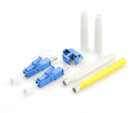
In the emerging SFF connector landscape, the LC connector is becoming the preferred transceiver connector for high bit rate applications (1Gb/s and above) due to its numerous advantages for transceiver design. More transceiver manufacturers support the LC interface than any other SFF connector, and LC transceivers are available from numerous sources for applications ranging from 10 Mb/s to 10 Gb/s.
Why Choose LC Connector?
The LC connector, developed by OFS Laboratories, represents the next-generation SFF connector. But why should we choose LC connector? The LC connector solution reduces the space required on panels, outlets and in closets by approximately 50% throughout the network. It simplifies moves, adds and changes and helps save you money. The LC connector uses an improved version of the familiar, user-friendly RJ-style telephone plug that provides a reassuring, audible click when engaged.
The new, one-piece design enhances the connector’s durability and meets side-load requirements of standard 2.5mm connectors. The connector can only be installed into the adapter in one orientation thus maintaining proper polarization and alignment. The straight-in motion significantly reduces debris and enhances optical performance. The unique combination of small size and the click of connectivity make LC connector the right choice for today’s high performance networks.
The LC Connector in Fiber Management and Transceivers
The LC connector system was designed specifically to address the needs of increasing network interconnect density. In the past, fiber management systems have required twice as many individual connectors as copper systems, hence, crowding racks and closets with additional patch bays, management hardware and line terminating electronics. The LC connector provides the potential for twice the interconnect density in closets and racks when compared to a SC connector. Although, there is a point at which additional density cannot be utilized because of the difficulty in fiber routing inordinately large cable counts. Also at issue in these higher density racks, is the problem of disturbing adjacent circuits in MACs. Most important in fiber management, is the decreased footprint of the LC on electronics (hubs, switches, etc.) for fiber transceivers.
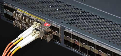
Original SFF transceivers (GBICs) on equipment have now been overshadowed by the SFP transceiver. Equipment vendors are starting to offer SFP on switches/NICs for 1Gb/s Ethernet. The optical receptacle on the SFP for Fibre Channel and Gb/s Ethernet is the LC connector. Most major transceiver vendors now sell SFPs with the LC interface.Figure 2 shows a 1000BASE-SX SFP (eg. TL-SM311LM) with LC duplex connector. For example, On 200 pin XenPAK transceivers, only SFF options are specified in the Multi Source Agreement (MSA). The LC is also used in competing transceivers such as XenPAK, X2 and XFP. 10Gb/s Standards are driving network planners to upgrade infrastructure hardware (fiber, cable management and interconnect) and to prepare their network Storage Area Networks and Fiber Backbones to be able to utilize these high-speed transceivers. For example, SFP-10GB-SR is 10GBASE-SR SFP+ that can transmit 10Gb/s on the LC connector.
Conclusion
Based on a wide range of criteria that cover issues relevant to infrastructure requirement, the LC connector offers clear advantages over its performance. With LC connector system, users effectively double interconnect density without the added expense of additional fiber management systems.
Posted by: angelina at
02:07 AM
| No Comments
| Add Comment
Post contains 679 words, total size 6 kb.
April 12, 2016
Small form factor pluggable (SFP) optical transceiver nowadays is commonly utilized in the telecom field for Ultra-high-speed transmission applications as well as for low-cost applications. Characterized by small form-factor, pluggable and self-diagnose, Gigabit SFP transceiver becomes the most popular application for fiber optic systems including asynchronous transfer mode (ATM), FDDI, fiber channel, fast Ethernet and gigabit Ethernet, and synchronous optical network (SONET)/synchronous digital hierarchy (SDH). SFP transceiver has dominated the market over a long time. Recently many vendors provide SFP transceiver with different specifications, but SFPs from Cisco are the standardized optical transceivers which are greatly favored by users. People may know what SFP transceiver is, but do they really know about SFP transceiver? The following article will offer a brief introduction to Cisco SFP first, then go further to the basics of the SFP transceiver.
Cisco SFP Module
Cisco industry-standard SFP modules can link your switches and routers to the network as shown in Figure 1. This hot-swappable device plugs into a Gigabit Ethernet port or slot. SFP transceiver are available in optical or copper models that can be used on a wide variety of Cisco products and intermixed in combinations of 1000BASE-T, 1000BASE-SX, 1000BASE-LX/LH, 1000BASE-EX, 1000BASE-ZX, or 1000BASE-BX10-D/U on a port-by-port basis.
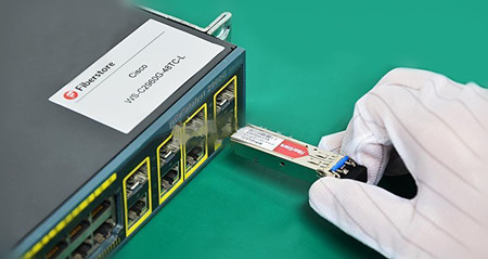
Take 1000BASE-LX/LH SFP as an example, it is compatible with the IEEE 802.3z 1000BASE-LX standard for both multimode and single-mode fibers. The 1000BASE-LX/LH SFP like GLC-LX-SM-RGD, operates on standard single-mode fiber-optic link spans of up to 10 km and up to 550 m on any multimode fibers. When used over legacy multimode fiber type, the transmitter should be coupled through a mode conditioning patch cable. Some people may feel confused about the term—1000BASE-LX/LH. In fact, it is created by telecommunication vendor, but not a ratified standard. Cisco GLC-LH-SM is also a type of this SFP transceiver that is compatible with 1000BASE-LX standard. The only difference between GLC-LX-SM-RGD and GLC-LH-SM lies in the function of Digital Optical Monitoring support. Since we are familiar with the Cisco SFP transceiver, let’s move onto the structure of SFP.
The Structure of SFP
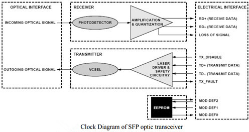
SFP transceiver is called Mini-GBIC for its smaller form-factor structure. A low-cost fiber optical transceiver circuit typically includes transmitter and receiver. The transmitter is composed of LD, Reference generator, laser bias circuit, PECL Input buffer, Laser modulation-circuit, Laser bias circuit, Automatic power control, and Failure detection. The receiver is made up of PD, Input biasing, Auto-zero circuit, power supply decoupling &optimizing sensitivity, lever detector and so on. A photodiode preamplifier, an active band-pass filter, and an instrumental amplifier is experimentally achieved. Using the proposed circuit for measurement and on-line automatic monitoring, the efficiency of fiber-optic characteristics monitoring can be enhanced and on-line noise interference can be suppressed. The transfer functions and frequency response of the optical receiver are derived.
Optic Transmitter and Receiver
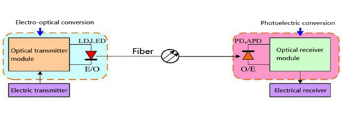
The key component of an optical receiver is its photo detector. The major function of a photo detector is to convert an optical information signal back into an electrical signal (Photocurrent). The photo detector in today's fiber - optic communications systems is a semiconductor photodiode (PD). This miniature device is usually fabricated together with its electrical circuitry to from an integrated package that provides power-supply connections and signal amplification.
The Working Principle of SFP Transceiver
From the above diagram, we can see that a SFP transceiver contains both transmitter and receiver in a single module. But how does a SFP transceiver work? In fiber optic data links, the transmitter takes an electrical input and converts it to an optical signal, which is coupled with a connector and transmitted through a fiber optic cable. The light from the end of the cable is coupled to a receiver, where a detector converts the light back into an electrical signal. In short, as the core of the optical communication devices, optical transceiver module completes optical signal light-electricity/electricity-light conversion function.
Conclusion
After going through this passage, you may have a clearer mind about the SFP transceivers. High performance and low cost SFP optic transceiver is highly desirable for fiber optic communications, but we can’t ignore the fact that SFP can only support up to 4.25 Gbps. For higher data rate like 10GbE or 40GbE, there are other optical transceivers to support them.
Posted by: angelina at
02:27 AM
| No Comments
| Add Comment
Post contains 862 words, total size 7 kb.
April 07, 2016
Since most data centers today are fueled by more data and great bandwidth, all optical technology including optical transceivers, must face the increasing demand for bandwidth. The technology needs to meet the bandwidth requirements not only for storage and switch applications but also for server applications. From the old 100 mbqs to the existing 40/100G Ethernet, optical transceivers has improved itself to keep path with the higher data rate. Here is what you need to know about optical transceivers and server technology.
Optical Transceivers: Smaller, More Affordable and Less Power Hungry
Network designers require transceiver modules that consumes less power and costs less while being smaller in size. For instance, the packages for optical transceivers are shrinking. They evolved from a 4" x 3.5" footprint to a 2.3" x 0.68" package. This is an essential evolution for optical transceivers as it allows the overall footprint of servers to decrease, making data centers smaller and more streamlined.
In addition, optical-transceiver power consumption has dropped from 10 W to 3 W or lower—a significant stride that has enabled designers to get more out of transceiver technology. Lower power consumption means lower prices in the design and in power costs. These savings are incredible for people in the technology field.
Port density is another important factors in transceiver design. Most data centers consist of multiple racks of switching equipment that can achieve high speeds. To control costs, designers have refined their designs and tried to improve their manufacturing process technologies to assist with this effort. Increasing port density is just one way to decrease system costs.
The Evolution Path of the Optical Transceiver
As noted before, optical transceivers that met the above requirements are typically recognized in the technology world through the SFP multi-source agreement (MSA). Nowadays, the data center have consolidated around optical transceivers in the SFP form factor for server access and around QSFP transceivers for switch-to-switch interconnects. Moreover, when the distance to the access port is less than 5 meters, direct attach copper cables are usually utilized while active optical cables are used for longer distances.
SFP+ (Enhanced Small Form-factor Pluggable ) transceiver plays a key role in 10G transmission with its advantage of compactness, performance and cost savings. For example, JD092B just like other SFP+ modules are widely used in 10G access ports for a long time. However, the situation will be changed in the near future when the access speed increases to 40G and the 10G access ports turn to QSFP. QSFP transceiver is a parallel transceiver which accept 4 electrical input lanes, and operate at 4 x 10 Gbps. Today, 40G QSFP+ like JG661A is widely deployed in data center switching fabrics and ramping up hard as data centers deploy 40GbE, particularly as a high-density 10G interface via breakout cables.
However, IHS Infonetics released a research in May this year which said QSFP28 modules will be deployed in high volumes as data centers transition from 40G to 100G switching fabrics starting in 2016. What’s QSFP28? As we know, the first-generation QSFP transceivers are equipped with four Tx and Rx and each channel has a rate of 10 Gbps. But now each channel of QSFP can transmit and receive data up to 28 Gbps thanks to the development of technology. This type of transceiver is called QSFP28 which is a new trend for 100G applications.
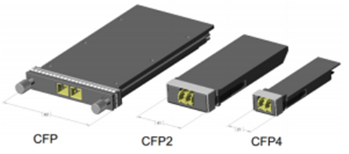
The widely recognized path to achieve 100G is "10GbE-40GbE-100GbEâ€. And the first fiber optic transceivers that were shipped with 100G transceivers were CFP. But CFP2 soon came along and achieved 5 x 25G (or 10 x 10G) lane electrical interface while it reduced the form factor by half of CFP. Even so, it costs too expensive and the its footprint is too large to trigger mass deployment. After CFP2, CFP4 which is half the size of the CFP2 has been launched. Meanwhile, there is another form factor namely QSFP28 mentioned above competing with it.
Optical Transceivers and Server Technology Affect Each Other’s Performance
Increased bandwidth is the everlasting topic of telecom field. And just as the saying goes, a man without distant care must have near sorrow. To cope with the ever-increasing bandwidth, every designer must find solutions that will optimize the systems they are designing or implementing for future proofing.
Despite how revolutionary optical transceivers were back when it was first created, it was a rudimentary tool at best. The demand for high port density transceivers started back in 2003 and since then, these devices have become increasingly smaller in a short amount of time. Optical transceivers with smaller packages actually play an important role in reducing overall server footprint, and smaller transceivers means smaller and more streamlined data centers.
Apart from making data centers smaller, the reduction of transceiver sizes also means that it uses less power, which in turn means lower prices as far as power costs and designing is concerned. This is a significant development in transceiver technology, and is shaping the way designers create these devices and get more out of it as an innovative technology.
Data centers are processing tons of data and need to retrieve at record speeds, which requires that every aspect of the design be optimized, including the optical transceiver technology. The above article has concluded several points about how optical transceiver react to the server technology.
Posted by: angelina at
06:11 AM
| No Comments
| Add Comment
Post contains 891 words, total size 7 kb.
April 01, 2016
Nowadays one and 10 Gbqs data rates are not adequate to meet the continued requirement for expansion and scalability in the data center, thus technology evolves and standards are completed to define higher data rates such as 40/100G Ethernet. In the meanwhile the cabling infrastructures installed today must provide scalability to accommodate the need for more bandwidth in support of future applications. OM3 and OM4 multimode cabling solutions have been proven to be a cost-effective solution for 40G data center. Today’s article will make you familiarize with this new Gigabit Ethernet and OM3/OM4 cabling to help you smoothly upgrade to 40G Ethernet.
Multimode Fibers in Data Center
Multimode fiber is more popular in data centers than singlemode fiber. Many people may know the reason—budget. Because the price of multimode fiber is typically much lower than singlemode fiber. Additionally, multimode fibers utilizes the low cost 850nm optical transceiver for both serial and parallel transmission. While singlemode fiber uses the expensive 1310nm and 1550nm transceiver and duplex fiber wavelength division multiplexing (WDM) serial transmission. Therefore, most data center designers would choose multimode fiber for 40/100G transmission.
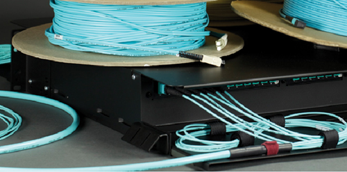
There are four common types of multimode fibers available in the market—OM1, OM2, OM3 and OM4. Recently OM3 and OM4 cables are gradually taking place of OM1 and OM2 multimode cable. OM3 and OM4 are laser-optimized multimode fibers with 50/125 core, which are designed to accommodate faster networks such as 10, 40 and 100 Gbps. Compared with OM1 (62.5/125 core) and OM2 (50/125 core), OM3 and OM4 can support high data rate and longer distance. This is why OM3 and OM4 is more popular in data center.
The Ratification of IEEE 802.3ba
The Institute of Electrical and Electronics Engineers (IEEE) 802.3ba 40G/100G Ethernet standard was ratified in June 2010. According to this standard, it includes detailed guidance for 40/100G transmission with multimode and singlemode fibers. But the standard does not have guidance for Category-based unshielded twisted-pair or shielded twisted-pair copper cable.
OM3 and OM4 are the only multimode fibers included in 40/100G standard. Because multimode fiber uses parallel-optics transmission instead of serial transmission due to the 850-nm vertical-cavity surface-emitting laser (VCSEL) modulation limits at the time the guidance was developed. Compared to traditional serial transmission, parallel-optics transmission uses a parallel optical interface where data is simultaneously transmitted and received over multiple fibers. Table 2 shows the IEEE standards for 40 and 100 GbE.
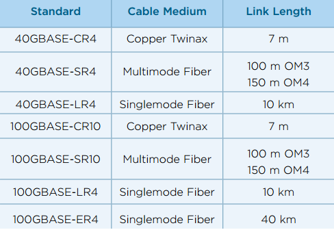
The 40G and 100G Ethernet interfaces are 4x10G channels on four fibers per direction, and 10x10G channels on 10 fibers per direction, respectively. For 40GBASE-SR4 transceivers, it utilizes multimode fiber for a link length of 100m over OM3 and 150m over OM4. QSFP-40G-SR4 is Cisco 40GBASE-SR4 QSFP+ that can both operate over OM3 and OM4 cables to achieve 40G connectivity just as FTL410QE2C.
OM3 or OM4?
As noted before, OM3 and OM4 can meet the requirement for 40G migration cabling performance, that’s why they are being widely utilized in 40/100G migration. But OM3 and OM4, which is better for your infrastructure? There is no exact answer to this question as numerous factors can affect the choice. The working environment and the total costs are always the main factors to be considered when selecting OM3 or OM4 multimode cable.
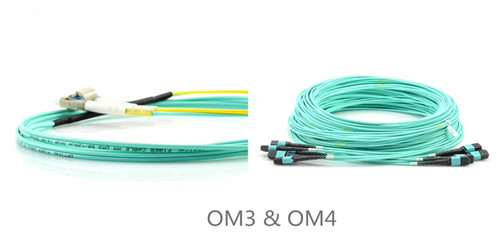
OM3 is fully compatible with OM4. They use the same optical connector and termination of connector. The main difference between them is in the construction of fiber cable that makes OM4 cable has better attenuation and can operate higher bandwidth at a longer distance than OM3. On the other hand, the cost for OM4 fiber is higher than OM3. As 90 percent of all data centers have their runs under 100 meters, choosing OM3 comes down to a costing issue. However, in the long term, as the demand increases, the cost will come down. OM4 will become the most viable product in the near future.
Conclusion
No matter choosing OM3 or OM4 for your infrastructure, 40G migration is in the corner. OM3 and OM4 multimode cable featured by the high performance and low cost are the perfect solution for 40/100G migration.
Posted by: angelina at
02:42 AM
| No Comments
| Add Comment
Post contains 684 words, total size 6 kb.
March 30, 2016
Recently 40GbE is gradually becoming the dominant Ethernet in the data center, which greatly promote the popularity of 40G components, especially 40G optical transceivers and 40G QSFP+ cables. 40G optical devices, featured by its unique specification, are designed to meet different interconnection applications in data center. It is known that 40G copper direct attach cables (Copper DAC), 40G Active Optical Cables (AOCs) and 40GBASE-SR4 QSFP+ optics are used in data center to achieve 40G interconnection. But according to IHS (a research company), 40G AOC won larger market share than the other two solutions in 2015 and the trend will keep going in 2016. So what makes it so popular in the data center? The following article will list several features of 40G AOC to give you a satisfying answer.
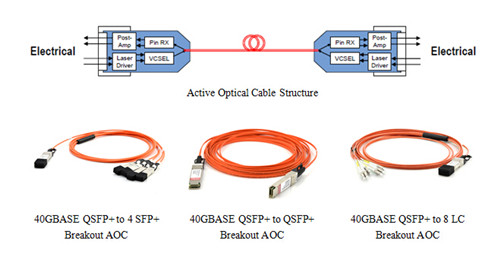
Before we come to the advantages of 40G AOC, let’s first have a brief overview of the 40G AOC cables. 40G AOC, is mainly used for short-range multi-lane data communication and 40GbE interconnect applications. It is a type of active optical cable terminated with 40GBASE-QSFP+ on one end, while on the other end, it can be terminated with QSFP+ connector, SFP+ connector, LC, SC, FC, and ST connector etc. The above picture shows three common types of 40G AOC.
40G AOCs have great advantages over 40G copper DACs like lighter weight, high performance, low power consumption, low interconnection loss, EMI immunity and flexibility. What’s more, when transmission distance reaches above 7 meters, 40G DAC is unable to reach. Just like QFX-QSFP-DAC-3M that is Juniper QSFP+ to QSFP+ passive copper cable with a link length of 3m. SR4 modules can support the same link length as AOC over OM3 cable, but has a better performance. Thus it is hard to tell which one is better than the other. The following part will illustrate from the next aspects—cost, Insertion Loss & Return Loss, Four-Quadrant Test and Digital Diagnostic Monitoring (DDM) to give you an objective solution about this.
40G AOCs cost lower than SR4 modules and do not need to use with extra fiber patch cables. In particular, 40G breakout AOCs, such as 40GBASE QSFP+ to 4 x SFP+ or 40GBASE QSFP+ to 8 x LC AOCs are cost-effective solutions to achieve 40G migration. For example, QSFP-4X10G-AOC1M is Cisco QSFP+ to 4SFP+ Active Optical Cable for a link length of 1 m. In additional, using AOCs, there are no cleanliness issues in optical connector and there is no need to do termination plug and test when troubleshooting, which can help user save more time and money.
Under the same case of transmission distance, the repeatability and interchangeability performances of SR4 module interface are not good as 40G AOC. What’s more, when different fiber optic patch cables plug into the module, it will have the different insertion loss and return loss. Even for the same module, this issue is existed. Of course, the related metrics such as the testing eye pattern will have no significant changes so long as the variation in and conformed to the scope. In contrast, an AOC with good performance is more stable and has better swing performance than SR4 modules in this situation. The following table shows the result of the repeatability test of SR4 module. From the data, it is clear to see that the repeatability performance of SR4 module is not stable.
The so called four-quadrant test is a testing under four combinations of input voltage and signal amplitude which are used to ensure the product to keep better performance even under the lowest and highest voltage and temperature situation. Four-quadrant test in wide temperature range is used to test the MTP/MPO interface and optical cable of AOC in order to ensure them not to be melted at a high temperature. Generally, the current products of AOC can all satisfy this demand. In addition, as an integration product, the performance of AOCs is more stable than SR4 modules which should be used with indeterminacy-performance MTP/MPO connectors. Unlike SR4 module, the quality index of AOCs is judged by electric eye pattern but not by light eye pattern.
DDM can help end users to monitor real-time parameters of the modules. Such parameters include optical output power, optical input power, temperature, laser bias current, and transceiver supply voltage etc. 40GBASE-SR4 QSFP+ modules with DDM function can ensure it’s optimal coupling by the ADC (analog to digital converters) value of real-time monitoring receiver when receive coupling. Thus, SR4 modules have better receiving sensitivity than AOC. However, at present, both SR4 module and AOC can not reach the function of real-time power monitoring.
To sum up, AOCs can avoid the influence of environment and vibration with integration and sealed design. Compared with 40G AOCs, DAC cables are more easier to manage as users do not need to do a series of termination plug and test on-site, but they do when using SR4 modules and patch cables.
Posted by: angelina at
02:52 AM
| No Comments
| Add Comment
Post contains 841 words, total size 6 kb.
March 26, 2016
In the past decades, the network speed has a great leap from 10Mbit/s in 1983 to today’s 40/100 Gbit/s. Thus new technologies have been developed to support the new transmission rate. Of which MPO technology with multifiber connector make the migration to 40/100 Gigabit Ethernet easier and more efficient, as it offers ideal conditions for setting up high-performance data networks in data centers to achieve greater bandwidth and handle future requirements. This article will briefly introduce the basics of MPO technology and its utilization in 40G Ethernet.
Shedding Light on MPO Connector
It is known that MPO connectors (known as multi-fiber push-on or multi-path push-on) can contact up to 72 fibers in a single connection. A connection must be stable and its ends correctly aligned, which is essential for achieving the required transmission parameters. A defective connection may even damage components and cause the link to fail altogether. MPO connectors are available in a female version (without pins), or a male version (with pins) as shown in the following picture. Noses and guide grooves (key) on the top side are the two other clearly visible features, which ensures the adapter hold the connector with the correct ends aligned with each other. Based on the placement of the key, two types of MPO adapters are available. One is "key-up to key-downâ€. It means the key is up on one side and down on the other. The two connectors are connected turned 180° in relation to each other. The other one is "key-up to key-upâ€. It means both keys are up. The two connectors are connected while in the same position in relation to each other.
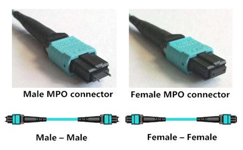
Three Common Types of MPO Cables
MPO cable has the advantages of shorter installation times, tested and guaranteed quality and greater reliability. It has several different kinds of types.
Trunk Cables: trunk cables serve as a permanent link connecting the MPO modules to each other. They are available with 12, 24, 48 and 72 fibers. Their ends are terminated with 12-fiber or 24-fiber MPO connectors according to customer’s choice. These trunk cables like 12 fibers MPO trunk cable could help to create a simple, cost-effective 40G networking by installing a structured cabling system. MPO trunk cable requires greater care in planning but has a number of advantages, such as higher quality, minimal skew, shorter installation time, better protection, smaller volume of cable and lower total costs.
Harness Cables: harness cables provide a transition from multifiber cables to individual fibers or duplex connectors. For instance, 8 fibers 12 strands MPO harness cable has eight LC high fiber density connectors and a MPO connector, which is convenient for wiring and management system in 40G network with stable performance.
Y Cables: Y cables are generally used in the 2-to-1 version. A typical application is to join two 12-fiber trunk cables to a 24-fiber patch cord as part of a migration to 100 GbE. The rather rare version of 1 to 3 allows three eight-fiber MTP connectors to be joined to a 24-fiber permanent link, e.g. for migration to 40 GbE.
MPO Technology in 40 Gigabit Ethernet Cabling
OM3 and OM4 fiber optic cables terminated with MPO/MTP connectors are dispensable for parallel optical connection. These are the ingredients for 40 GbE technology in a structured cabling environment. Parallel optical channels with multifiber multimode optical fibers of the OM3 and OM4 are used for implementing 40 GbE. The small diameter of the optical fibers poses no problems in laying the lines, but the ports suddenly have to accommodate four or even ten times the number of connectors. This large number of connectors can no longer be covered with conventional individual connectors. So 802.3ba standard incorporated the MPO connector for 40GBASE-SR4. 40GBASE-SR4 QSFP+ modules like QSFP-40G-SR4 can support link lengths of 100 meters and 150 meters, respectively on OM3 and OM4 multimode fibers with a 12-fiber parallel MPO/MTP female connector. We can achieve 10G to 40G migration up to 100m or 150m, respectively on OM3 and OM4 MTP to LC break out cable as shown in Figure 2.
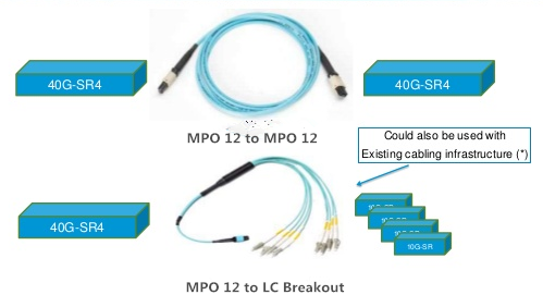
Some Tips About MPO Connection
- Always use one male connector and one female connector plus one MPO adapter when creating a MPO connection (see the following picture).
- Never connect a female to a female or a male to a male. It should be connected with a male and a female as stated above. With a female-to-female connection, the fiber cores of the two connectors will not be at the exact same height because the guide pins are missing. That will lead to losses in performance. A male-to-male connection has even more disastrous results. There the guide pins hit against guide pins so no contact is established. This can also damage the connectors.
- Never dismantle a MPO connector. The pins are difficult to detach from a MPO connector and the fibers might break in the process. In addition, the warranty becomes null and void if you open the connector housing.
Summary
Featured by its high density, flexibility and reliability with scalable, upgradeable properties, MPO technology can better satisfy the increasing need to upgrade to 40/100G. Just don’t forget to follow the above connection rules.
Posted by: angelina at
02:06 AM
| No Comments
| Add Comment
Post contains 868 words, total size 7 kb.
March 24, 2016
What is the difference between SFP+ and SFP?
The pinouts of SFP and SFP+ connectors are identical. However, SFP has a maximum data rate of 5Gb/s whereas SFP+ is designed for 10Gb/s. The SFP receptacles and plugs are not as well impedance matched as SFP+ receptacles and plugs. Also SFP+ cable is designed for 10Gb/s whereas SFP cable may not be able to satisfactorily transmit that rate.
What is the distance supported by the SFP+ SR transceiver?
The supported distance is up to 300 meters depending on the quality of the multimode fiber (MMF) you use. Quality of MMF is listed as OM1 (up to 33 meters), OM2 (up to 82 meters), OM3 (up to 300 meters), and OM4 (up to 400 meters). Check with the supplier for the cable distance supported. Take GP-10GSFP-1S as an example, it is Dell Force10 10GBASE-SR SFP+ covering a distance of 300m over OM3 multimode cable.
Can I use SFP+ cables in SFP ports?
Yes, SFP+ cables are compatible to SFP ports and will work fine. SFP cables are not compatible to SFP+ ports. SFP+ receptacles have a mechanical feature to prevent engaging SFP plugs.
Do Fiberstore’s SFP+ direct-attach Twinx passive cables work with Cisco or other third-party switches?
Fiberstore’s direct-attach SFP+ Twinx passive cables are fully compatible with the original brand like Cisco. For example, SFP-H10GB-CU3M is Cisco SFP+ to SFP+ passive copper cable from Fiberstore which is fully compatible with Cisco switch. The following image shows that our professional trained staff tests the compatibility and interoperability of each optics to make sure our customers to receiver the optics with superior quality.
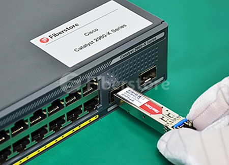
What are the distances supported by cables to use with the 10GBase-T ports? Does Fiberstore offer these cables?
Data centers have a large installed base of Cat 5/6/7 twisted pair cables for the last decades—initially for 1000BASE-T and now for use with 1/10GBase-T infrastructure. Fiberstore does offer these cables since they are industry standard and widely available from us in various lengths and colors. Distances supported at 10 Gbps speed:
- CAT 6A and CAT 7 cables supporting 100 meters
- CAT 5e and CAT 6 cables supporting 55 meters
Do the SFP+ optical transceivers support 1 GbE operation?
Yes, they support 1GbE and 10 GbE dual rates and can be configured for 1 GbE.
Will the SFP+ optical transceivers auto-negotiate between 1 GbE and 10 GbE?
Auto-negotiation is not supported between the 10 GE and 1 GE speed. The transceiver must be manually configured to operate at 1 GE speed.
How do I use the SFP+ ports for 1000BASE-T?
You need to purchase Fiberstore’s SFP+ to 1000BASE-T Media Converter. (SFP+/Copper RJ45), part number FMC-1SFP/1RJ45-GB.
Is TwinX same as Twinax?
Yes.Does the Twinx copper cable plug directly into the NIC and the switch?
Yes, the copper cable has an SFP+ or QSFP connector on both ends of the cable that directly plugs into the corresponding ports of the switch and NIC.
Should I use optical transceivers with the SFP+ and QSFP direct-attach Twinx copper cables?
No. These are direct-attach Twinx cables and come with connectors that plug directly into the SFP+ port or the QSFP port of the switch/NIC on either end. Transceiver cannot be used.
What is the advantage of SFP+ Twinx copper cable?
It is a low-cost option for shorter distances up to 5 meters.
Is 10GBase-T same as 10GBASE-T?
Yes. 1GBase-T is shorthand for 1000BASE-T and 10GBase-T is same as 10GBASE-T; they are the twisted pair implementations of 1 GbE and 10 GbE respectively.
What are the SFP+ copper cables provided by Fiberstore?
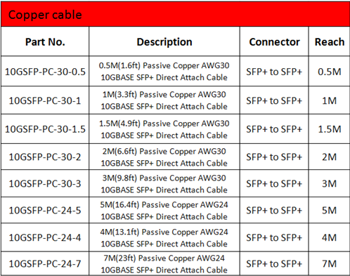
Posted by: angelina at
02:38 AM
| No Comments
| Add Comment
Post contains 604 words, total size 6 kb.
March 18, 2016
As the need for high data rate increases and the supporting optical devices becomes more affordable, many network designers are inclined to upgrade their infrastructure to higher-speed network like 10 Gigabit Ethernet. Currently 10G Ethernet is ubiquitous in data center. But do we really know about 10 Gigabit Ethernet? The following passage will provide some basic information to help you smoothly migrate to 10 Gigabit Ethernet.
Fiber cable type, 10 Gigabit Ethernet physical interface and fiber optical transceiver module are the crucial components of 10GbE deployment. Table 1 demonstrates the standard fiber cables, physical interfaces, and transceiver modules that can be applicable to 10 Gigabit Ethernet.
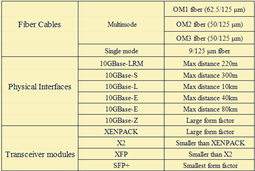
10G SFP+ transceiver, as an essential component to support 10G network, will be introduced in the next part. SFP+ supports speeds of 10Gbps or higher over fiber. The SFP+ product family includes cages, connectors, and copper cable assemblies. It is also similar to the performance requirements of SFF-8431 and also supports 8G Fiber Channel and 10G Ethernet applications. Take 46C3447 as an example, it is 10GBASE-SR SFP+ that can support a distance of 300m over OM3 cable.
10G Ethernet Fiber Cabling
As 10G cabling standards develop over time, there are three different copper cabling technologies for 10 Gigabit Ethernet. First, 10GBase-CX4 is the first 10 Gigabit Ethernet copper standard. It’s relatively economical and allows for very low latency. But the form factor is too large for high density port counts in aggregation switches.
Second, Small Form-factor Plus (SFP+) is the latest standard for optical transceivers. 10 Gb SFP+Cu direct attach cables (DAC) directly connect into an SFP+ housing. It’s the best copper solution for servers and storage devices because it has low latency, small form factor and reasonable price.
Third, 10GBase-T is a fully IEEE compliant Ethernet transport technology standard, as defined by IEEE 802.3an-2006. 10GBase-T is to run 10 Gigabit Ethernet over CAT6a and CAT7 copper cabling up to 100 meters. 10GBase-T copper twisted-pair cabling can enable the earlier 10MB, 100MB and 1GB operation. However, 10GBase-T still needs to be improved on its price, power consumption and latency.
SFP+ Direct Attach Cables
SFP+ direct attach cables integrate SFP+ compatible connectors with a copper cable into a low-latency, energy-efficient, and low-cost solution. SFP+ direct attach cables offer the smallest 10 Gigabit form factor and a small cable diameter for higher density and optimized rack space in 10GbE uplinks and 10 Gigabit Fiber Channel SAN and NAS input/output connections. To use SFP+ direct attach cables can save you a lot compared with fiber optic solutions. And it can still provide lower latency and save up to 50% power consumption per port than other copper twisted-pair cabling systems. For example, JD097C is HP SFP+ passive copper cable that can support a link length of 3m.
SFP+ direct attach cables can also provide enhanced scalability and flexibility. The cables connect several servers or storage devices together in a single rack. Thus, it reduces the use of intermediate patch panels. And it’s easy to move racks or deploy one rack at a time since the cabling outside of the rack is limited to the main switch connection.
Conclusion
The increase in network bandwidth is driving the need to develop new products that will handle the network traffic and improve network performance. The 10GbE is presently underway to create a brighter future of fast-speed. And after years of development, there has been various different form factors and optics cable types introduced including XENPAK, X2, XFP, SFP+ and SFP+ cable.
Posted by: angelina at
03:11 AM
| No Comments
| Add Comment
Post contains 586 words, total size 5 kb.
30 queries taking 0.1006 seconds, 115 records returned.
Powered by Minx 1.1.6c-pink.

