



December 29, 2016
Fiber optic technicians are aware that dirty connections can cause attenuation, but they may not realize that it can also cause bit errors or slowdown of the network. Therefore, keeping the fiber optic connector endfaces clean is one of the most overlooked aspects of fiber optic maintenance and troubleshooting. Today’s article will describe the detailed information about how dirty fiber optic connector can cause slowdown of the network.
Brief Overview of Fiber Optic Connectors
A fiber optic connector is urgently needed to the industry owing to the lower loss, lower cost, easier to terminate or solved some other perceived problem. As a result, about 100 fiber optic connectors have been introduced to the marketplace, but only a few represent the majority of the market. Commonly used fiber optic connector types like the SC, FC, LC, ST, MU, E2000, MTRJ, SMA , DIN as well as MTP & MPO etc, which are widely used in the termination of fiber optic cables, such as fiber optic pigtail, fiber optic patch cables and so on.
How Does the Dirty Fiber Optic Connector Cause Bit Errors?
Of course, the dirty fiber connection will cause bit errors as the contamination degrades the signal quality. In fact, the signal comes in a beam of light traveling through the fiber’s core. When the light travels through the fiber core, it has a refractive index value. But when the light beam comes into contact with end face contamination, it will enter a second medium which has different refractive index value. That’s the reason why it causes the bit error rates.
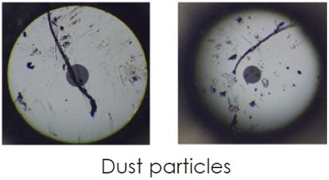
Figure 1: dust particles under the microscope
Sometimes, in fiber optic network, we need to mate two fiber optic connectors together. Will the mating prevent fiber optic connector from contamination? The answer is yes. There is no need to worry about dust with physical contact connectors as long as they were cleaned before the mating process. When the two ferrules are physically mated, the mating force for most single fiber industry standard connectors is around 1kg or about 2.2lbs. If you calculate the force of what 2.2lbs in a 200μm, that comes to 45,000psi which is why contaminate migration is not a problem even in a dusty environment. The following part will provide some answers to some common questions of end users.
Will the Dust Cap Make Fiber Endface Clean?
No, customers should never assume that a capped cable assemblies is clean when taking out of the bag. Dust and mold release agents are the two common contaminates but nearly invisible for the human eyes. The primary purpose of the end cap is to protect the ferrule end face from scratch and pitting defects. It does not protect the ferrule end face from contamination.
If a customer buys a new fiber jumper from the manufacturer and inspects it after taking the end caps off, it would not be uncommon to see some small amount of on contamination on the endface. This does not mean that the jumper manufacturer’s quality process are lacking. All manufacturers experience this. The customer just needs to work smartly and realize that the end cap is just for protecting against scratches. The best practice is to inspect the ferrule, clean if necessary and re-inspect before mating. If the customer does not have a ferrule scope available, then cleaning both connectors end faces before mating will significantly reduce the likelihood of damage and cross contamination.
How to Keep the Fiber Optic Connectors Clean?
Keeping fiber connections clean is different from any other type of cleaning due to the relative sizes of the connectors compared to the particles and contaminants that typically reside on them. Also we need to be diligent in their maintenance by cleaning the connectors every time before they are mated and after each un-mating. Static charges attract dust to the fiber connectors and prevent them from falling off even when blown with a can of compressed air. As we have discussed in the above article, dust caps are primarily used to protect the ferrule and can actually make a clean connector dirty due to their tendency to keep a static charge.
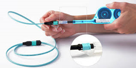
Figure 2: use one-click cleaner to clean the MPO cable
The mechanical cleaning tools like the One-Click cleaners are widely used in the optical fields. . One-click cleaner is designed to clean male connectors, female bulkhead adapters, fiber patch cables and test equipment. It cleans the ferrule endface removing from dust, oil and other contamination without scratching the endface. Although it is the most cost-effective and time-saving solution for cleaning fiber optic connectors, it has a limited contact region and will never be able to clean the connector’s end face. Therefore, another fiber optic cleaner has given to birth—Fiber Optic Cassette Cleaner. The cassette cleaner can wipe away contamination from optical connector endface with ease. I’s very easy to use and suitable for LC/MU/SC/FC/ST/MPO/MTRJ connectors. Usually, the body of this cleaner is made from antistatic materials which will not produce dust.
Is Dry Cleaning a Better Solution?
Besides the mechanical cleaning tools, there are two basic methods :dry cleaning and wet cleaning. There are two distinct advantages a wet cleaning process has over the dry process. The first process is static dissipation and the second is the cleaning solvent’s ability to loosen up harden contaminates from the ferrule end face without causing permanent defects to the end face.
On the other hand, the dry wiping process that an operator would do using a Fiber Optic Cassette Cleaner or One-Click cleaner relies on contact friction to remove contamination. When two materials are rubbed together, there is a transfer of electrons between the two surfaces and the imbalance on the surface creates a charged electric force we call static electricity. The two surfaces, one charged positive and the other negative, will try to pull in surrounding particles to being the charge back into a neutral balance. This attraction pulls in the dust particulates in the air and the wear debris on the connector body and adapter. The introduction of a cleaning solvent during a wet-dry cleaning process introduces static dissipative medium for the charge so that it does not stay on the ferrule surface.
Conclusion
End users should be wise to think of the environment his connectors are being exposed before learn to keep fiber optic connector clean. Because a large enough piece of dust particulate residing somewhere on either ends will create problems. The best practice to avoid long-term problems and extend the life of your optical assemblies is to always inspect and remove any contamination regardless of the connector type. FS.COM offers a full range of fiber optics that can cater to your specific requirement. Bulk Ethernet cable, fiber jumpers, transceivers and DAC/AOC cables are in great selection.
Posted by: angelina at
08:26 AM
| No Comments
| Add Comment
Post contains 1135 words, total size 8 kb.
December 22, 2016
Many telecom professionals anticipated that copper cable would eventually be replaced by the fiber optic cable owing to its poor performance in higher-bandwidth application. However, copper cables like cat6/cat6a cable that can support up to 10Gbqs have proven themselves and been widely deployed in the home or office buildings. But for the copper cable, there exists the debate about unshielded twisted pair (UTP) vs. shielded twisted pair (STP). Thus this article aims to provide the detailed information about UTP and STP cables to help users make an informed decision.
Alien Crosstalk (ANEXT)
We all know that copper cable suffer from higher signal loss than fiber optic cable and can be easily interfered by the nearby powers or generator. Alien crossstalk is the performance parameter in copper cables, especially the UTP cables. The following image demonstrates different reactions of the UTP and STP cables to the ANEXT.
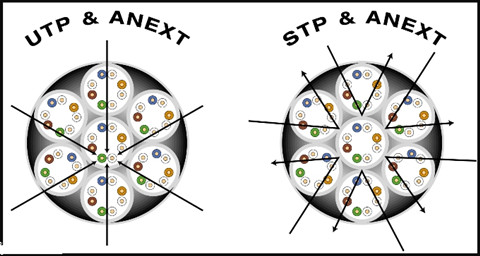
So what is the Alien crosstalk? Alien Crosstalk (ANEXT) is a crosstalk that occurs between adjacent cables and connecting hardware. Alien crosstalk in high-speed application is far more severer than in lower-bandwidth infrastructure. It might not be a problem at the lower frequencies of cat 5e and cat 6a cables, but the limiting noise source of the cat 6a systems.
In UTP copper cabling, the alien crosstalk will increase when adjacent cables are close proximity, which is indeed a nightmare to users. Therefore, it is typically recommended to let cat6a cable lay loosely in pathway instead of tight, twisted bundles. People usually have the misconception that if they use STP cables, then alien crosstalk would not be a problem. However, if the shield is not terminated correctly even a shielded system can fall foul of alien crosstalk.
UTP and STP Copper Cable
Twisted pair cables are widely used in transmitting information, especially across great distances. The twist in the wire cancels out any magnetic interference that may develop in the wiring. There are two common types of twisted pair cabling, STP and UTP.
Unshielded Twisted Pair (UTP)
Unshielded twisted pair cable has four pairs of wires inside the jacket. Each pair is twisted with a different number of twists per inch to help eliminate interference from adjacent pairs and other electrical devices. Unshielded twisted-pair cable does not rely on physical shielding to block interference. It relies instead on balancing and filtering techniques using media filters, baluns or both. Noise is induced equally on two conductors and is canceled out at the receiver.
With properly designed, manufactured and installed UTP cable, the network is easier to maintain than one in an STP cable plant, with its shielding continuity and grounding issues. UTP cables can be found in different categories, for instance, cat 5 UTP for specifications to 100 MHz and cat 6a UTP cables for specifications to 500 MHZ. Best buy Ethernet cable you can afford, most small business would purchase Cat 5e or Cat 6 cables.
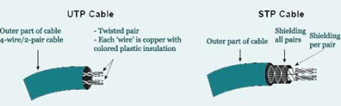
Shielded Twisted Pair (STP)
Shielded twisted pair cable contains a hidden metal coating that protects wires from radio and electromagnetic interference. How effective the shielding is depends on the material used for the shield, its thickness and frequency, the type of electromagnetic noise field, the distance from the noise source to the shield, any shield discontinuity and the grounding practices. Also, crosstalk and signal noise can increase if the effects of the shield are not compensated for.
When people install and maintain them properly, STP cables greatly reduce crosstalk. This enhances dependability and boosts data transmission speeds in buildings that contain microwave equipment, HVAC systems or radio transmitters. There are many acronyms used on the market to describe shielded cables, from STP to F/FTP; while many are often used synonymously, nearly all of them have different meanings. This blog provides basic information about each style, as defined by ISO/IEC 11801:200, to clear up the confusion.
F/UTP (FTP)
An overall foil shield (F) with unscreened twisted pairs (UTP). This cable is very much like common UTP cables, with the addition of foil underneath the main cable jacket. Another common name for this cable is FTP. F/UTP cables are common in 10GBaseT applications.
S/UTP
An overall braid screen (S) with unscreened twisted pairs (UTP). This is occasionally referred to as an STP cable, but beware: There are other shielded cables among this list that may also claim this term. To be sure, always check to see whether your cable will have any kind of overall barrier, and whether the individual pairs have their own shield.
SF/UTP
Both an overall braid screen (S) and foil shield (F) with unscreened twisted pairs (UTP). This cable is also occasionally referred to as an STP cable. Cables with an overall braided screen are very effective at protecting EMI from entering or exiting the cable, but heavier, thicker and more difficult to install than its UTP counterpart.
S/FTP
An overall braid screen (S) with foil screened twisted pairs (FTP). The ‘shield’ underneath the jacket is a braid, and each individual pair is surrounded by its own foil barrier. The purpose of the additional foil on individual pairs is to limit the amount of crosstalk between them.
F/FTP
An overall foil shield (F) with foil screened twisted pairs (FTP). Similar to F/UTP cables, these shielded cables are commonly used in 10GBaseT applications.
U/FTP
No overall shielding or braid (U) with foil screened twisted pairs (FTP). This type of shielded cable is commonly used in 10GBaseT applications as well.
To sum up
- STP cables are shielded, while UTP cables are unshielded.
- STP cables are more immune to interference and noise than UTP cables.
- STP cables are better at maximizing bandwidth compared to UTP cables.
- STP cable cost more per meter compared to UTP cables.
- STP cables are heavier per meter compared to UTP cables.
- UTP cables are more prevalent in SOHO networks while STP is used in more high-end applications.
Which One Should I Use?
A key factor in this decision is an analysis of how prevalent EMI will be in the installation environment. EMI is commonly caused by nearby motors, generators, air conditioners, and even office mainstays such as fluorescent lights and printers. EMI can cause crosstalk between circuits, resulting in degradation of data, increased errors and slower transmission rates.
While even UTP cables reduce some EMI, shielded STP cables more effectively block interference. STP cables are ideal for high-speed networks such as data centers where 10GBase-T networks are used because 10G Ethernet is significantly more sensitive to EMI. Shielded cables also come in handy when installers must run wires next to fluorescent lights, microwave ovens or powerful motors.
STP cables are also used in outdoor environments where the cables are exposed to the elements and man-made structures and equipment that may introduce additional interference. It also stops criminals from using jammers to interrupt communications between cameras and indoor monitors or recording equipment.
However, people use UTP cables in the vast majority of homes, offices, and even in large scale businesses due to its lower cost. Unshielded phone and network wiring performs well in most buildings. If you don’t have major concerns about interference, it’s wise to avoid the cost and complexity of STP wiring.
Note that shielded cabling is more expensive than unshielded cabling and more difficult to install; it’s stiffer, making it less flexible. The cable also has a larger diameter, taking up more space in conduit. UTP, on the other hand, actually provides faster transmissions in the absence of EMI. It’s less expensive to purchase, easier to install and has been the standard for many years, so it’s already in place in most existing installations.
Conclusion
It is really doesn’t matter whether you use STP or UTP cables, make sure to install high-quality cabling. High-quality cabling will get you out of the trouble, reducing long-term replacement and labor costs. FS.COM offers a full range of UTP and STP copper cables with great customer feedback. If you are still not sure what type of wiring you need, please visit fs.com.
Posted by: angelina at
09:16 AM
| No Comments
| Add Comment
Post contains 1332 words, total size 10 kb.
December 16, 2016
Nowadays more than one third of the popularity have access to the internet. Large enterprises already use the high-capacity fiber-optic access networks, and small- or medium-sized businesses also want to relieve the bottleneck of the copper-based access network and benefit from the fiber-based access network. Nonetheless, costs is one of the factors that small business would take into account. In fact, the cost of large-scale fiber optic deployments depends on a wide range of factors, including redundancy and survivability need, access to the closest fiber line, labor cost, Aerial vs. Underground, and the fiber maintenance cost. The following article concludes several factors that will have great impact on the costs of building a fiber optic network.
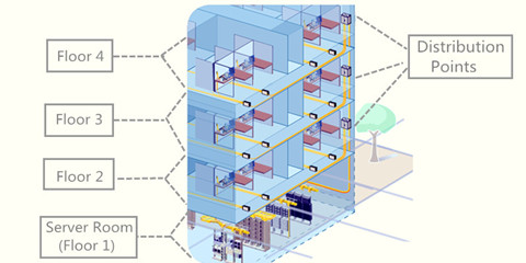
Figure 1 shows the layout of the fiber optic network in an office building.
Reminder:
Every building is situated differently, has different surroundings, different neighbors, and different physical dynamics influencing access to fiber lines, how much you’d have to spend on installation will be determined according to the specifics situation. Therefore, the factors listed below can not fit every situation. And we will not present the available materials that are likely to be used in you network as each installation requires its own assessment to determine final fiber optic network.
Redundancy and Survivability Needed
In a network designed with redundancy in mind, each portion of the network is constructed as part of a ring and economical construction is possible. On the other hand, when redundancy is constructed after the fact, it requires a custom cable pathway, usually doubling (or more) the construction cost.
Recently nearly 99 percent of the network will need two redundant physical paths from the network to its location, along with an electronic infrastructure to accommodate failure of a fiber route or an electronic component, and backup power of sufficient duration. And it also need to provide a 24-hour network operations center, a fiber repair crew, intrusion detection, and backup management and recovery facilities.
If network users do not require this level of availability, the network operator should determine their actual current and future requirements, and which subset of survivability and redundancy tools are needed. Ideally, any needs for physical redundancy will be included in the initial project design.
Labor CostsAlthough the fiber equipment costs have fallen, skilled labor costs have risen. So how can operators limit those high labor costs and still deploy a quality fiber network that can handle the bandwidth needs of today’s subscribers?
Labor typically forms the majority of the cost of construction—approximately 50 to 80 percent. Therefore the quantity of fiber strands and cables, a materials cost, is typically a secondary consideration. Labor costs are highly variable. For example, poor economic conditions may lead construction companies to reduce their fees, while mobilization of contractors may increase their bid rates if there is suddenly high demand for immediate construction. In general, large-scale ventures have an advantage in managing costs, because construction companies feel comfortable offering lower rates when they expect to profit from the volume and duration of a project.
Ability to Reuse Existing Infrastructure
Reuse the existing infrastructure is not only a cost-saving solution, but an eco-friendly option for overall users. There are a number of options for using existing cable infrastructure. For example, if there is sufficient space in the existing conduit, then you can take advantage of conduit by adding new capacity to your building, which will make your installation substantially simpler and cheaper. Furthermore, whether the existing conduit already lead straight up into your building, or it is configured through twists and turns will have a major impact on the costs of its installation. That’s it, winding paths are trickier than straight cables.
Let’s solve a problem in arithmetic. The cost of a 6-count fiber cable is $2,000 per mile, while an 864-count cable is $50,000 per mile, implying a marginal cost of approximately $50 per fiber per mile. Actual costs for fiber purchase or lease, of course, reflect market costs and depend on the total availability of fiber over the route—and are thus, typically, considerably higher; however, fiber lease or purchase may be a serious consideration over routes where construction is difficult or costly and considerable fiber has already been installed.
Aerial vs. Underground
Typical construction is a mixture of aerial and underground techniques, in part because aerial construction also is more vulnerable to extreme weather, particularly in wooded areas and areas with frequent ice and high winds. And another reason is that aerial construction may be more expensive when poles are crowded or when the utility pole owner charges high rates for access. Worst-case costs can be $100,000 per mile (which usually would lead a network owner to build underground or over another route).
Underground construction also has a wide cost range. In areas where restoration is not important and long continuous runs are possible, "plowing†the fiber into the ground is an inexpensive option—approximately $70,000 per mile. For more detailed information about aerial and underground construction, please see an article entitled "Whether to Go for Aerial or Underground Deploymentâ€.
Based on the estimated percentage of aerial and underground plant we identified in our field survey, we estimate that the difference between aerial and underground construction in Santa Cruz is more than $80,000 per mile, as shown in Table 2.
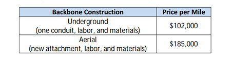
Table 2: comparison of estimated aerial and underground construction costs.
Cable Management
Of cause, wire management is the most important part of any installation, especially for data communication. For better cable management in server room or the data center, IT racks, fiber enclosures and patch panels should be used. To determine what type of panels you need, take into consideration the space that will be utilized for the network. If you are installing inside of a closet or other cramped quarters and need low density, wall mountable panel is the best choice because it does not take up a lot of room. If racks are already in place, or if there is enough room to install them, rack-mount tray is the best choice because it is sturdy and easy to access. Keep in mind that rack-mount tray does not protect against environmental conditions.
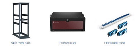
Figure 3 shows the required equipment for better cable management.
Open frame racks are suggested for this server room, which can provide more flexible cabling environment. The using of fiber enclosure and adapter panels should depend on the fiber count.
The Location of Your Network
The single greatest determining factor not only to how much installation costs, but also how difficult it is to accomplish. Is fiber local or close to your office building? Or do you have to cross a state highway to extend fiber into your site? The nature of the physical terrain that the fiber needs to traverse to reach your building becomes significant. If you have to cross a state highway to bring the nearest fiber to your building, overcoming that obstacle will significantly impact the overall costs. Special use areas such as historical sites can often cause a problem for bringing fiber directly to your building. If there are any of these sites nearby your location, they could potentially impact the costs of fiber installation, depending on the route fiber needs to take to your facility.
And when the fiber is brought to your building, do you have a telecommunications room with the necessary space for installation already available? If so, that will streamline your installation costs, and ensure connectivity continuity once the installation is complete. As you may be gathering, every potential wrinkle in the process of installing fiber has the potential to make it more complicated, and everything that does in fact represent a hurdle has the potential to make the final charges more costly.
Power for Fiber Technology
How easily is sufficient power for fiber accessible from your telecommunications room? If there is ample power available, or if an emergency generator can be used to insure up-time of activated service, then you will save in fees that would require the introduction of additional power capabilities.
Fiber Maintenance Costs
Fiber optic cable is resilient compared to copper cable and coaxial TV cable. The fiber itself does not corrode, and fiber cable installed over 20 years ago is still in good condition. However, fiber can be vulnerable to accidental cuts by other construction, traffic accidents, and severe weather. In other networks of this size, we have seen approximately 80 outages per 1,000 miles of plant per year.
The fiber optic redundancy from the hubs to the FDCs in the backbone network will facilitate restoring network outages while repair of the fiber optic plant is taking place. Depending on the operational and business models, you might be responsible for adds, moves, and changes associated with the network as well as standard plant maintenance. These items may include:
- Adding and/or changing patching and optical splitter configurations at hubs;
- Extending optical taps and laterals to new buildings or developments;
- Extending access to the FTTx network to other service providers;
- Relocating fiber paths due to changes such as the widening of roadways;
- Participating in the moving of utilities due to pole replacement projects;
- Tree trimming along the aerial fiber optic path.
Conclusion
If you are still with us, and concerns about the cost of the installing a fiber optic network, please do not feel hesitate to contact FS.COM for a free consultation. We’ll be happy to provide you with the perfect solutions that meets your specific needs, and clarifies all the above factors that contribute to the bottom line. We offer a full range of enterprise network solutions including the 10G/40G switches, optical transceivers, high-density fiber optic cables, etc.
Posted by: angelina at
04:17 AM
| No Comments
| Add Comment
Post contains 1612 words, total size 13 kb.
December 08, 2016
We can’t deny the fact that Cisco is one of the most important developers of network devices in the world. They supply a full range of switches including the Nexus, ME, Meraki, Blade, and Catalyst lines. Each of them is designed for unique applications, for example, Catalyst Switches is made for Campus Networks and Nexus Switches for Data Centers. Catalyst 4500-X series switch as one of the intriguing new switch of the catalyst lines, is a cost-effective, fixed aggregation for campus LAN network that brings in 10GbE uplinks. Featured with small size, high scale, this switch is warmly welcomed by overall users. Today’s article will provide some detailed information about this switch, and some advice about how to choose the right optical solutions.
Features of Catalyst 4500-X Series
Catalyst 4500-X switch is available in four versions: 40-port, 32-port, 16-port, and 8-port. Cisco offers seven different chassis of the series, namely Catalyst 4500X-16, Catalyst 4500X-24-IPB, Catalyst 4500X-24-ES, Catalyst 4500X-32, Catalyst 4500X-40, Catalyst 4500X-F-16, Catalyst 4500X-F-32. Remember to pick the right one that meets your needs. Compared with the Catalyst 3850 switch (also known as the 3750-X successor), we can clearly see its advantages, which has been displayed in the below part.
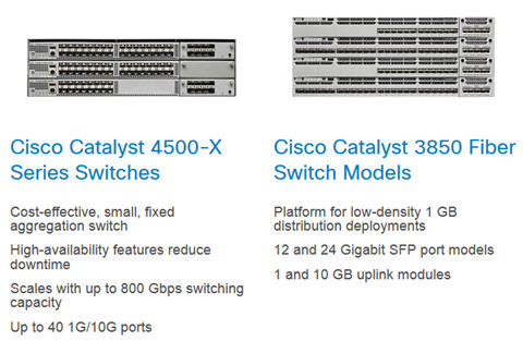
- Cisco Digital Network Architecture
Only Cisco delivers a digital-ready approach that starts at the edge and extends to where applications reside.
- Platform scalability
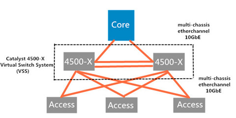
The Cisco 4500 offers up to 800 Gbps of switching capacity. It can scale up to 1.6-Tbps capacity and provides resiliency with Virtual Switching System (VSS). VSS refers to a method that can combine two physical switches into one logical switch to achieve physical redundancy, spanning free blocking elimination and increased bandwidth. That means any two Cisco catalyst 4500-X series switch can be pooled together into a VSS.
- High availability
Simplify network deployment and management with easy virtual networks (EVN). The 4500-X also reduces energy costs. Furthermore, device resiliency features such as redundant hot-swappable fans, power supplies, and AC to DC failover and vice versa remove single points of failure in the network.
- Application monitoring
Get enhanced application monitoring through Flexible NetFlow and 8 ports of line rate bidirectional Switched Port Analyzer (SPAN)/Remote Switched Port Analyzer (RSPAN). Cisco IOS XE Software provides the ability to host third-party applications.
- Security
Enhance security with support for Cisco TrustSec and Flexible NetFlow technologies.
- Simplified operations
The 4500-X offers support for Smart Install Director. Customers gain a single point of management for zero-touch deployment of new switches and stacks in campus and branch networks.
How to Choose the Optical Solutions for Catalyst 4500-X?
As noted before, the 4500-X ports support both SFP+ 10GbE optics and 1GbE modules. No matter what type of Catalyst 4500-X series switch you use, you will face the same problem of how to select the right one. The following image shows a 32-port chassis catalyst 4500-X series switch (front view).
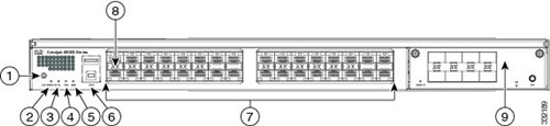
1—UID LED and switch combination2—STATUS LED3—PS1 LED4—PS2 LED5—FAN LED6—USB ports7—The 16 port version of the chassis does not have the block of 16 ports on the right side of the front panel.8—Port status LEDs9—8-port uplink module (Included as part of the WS-C4500X-24ES and WS-C4500X-40ES chassis; available as an optional upgrade on the other Catalyst 4500-X series chassis)
As noted before, each Ethernet port requires either an SFP or SFP+ transceiver be installed to operate. The common used pluggable modules includes the three types—copper cable with RJ45 connector, direct attached cable and the pluggable transceiver module with the fiber patch cable. Before making the move, it is necessary for us to review the basic knowledge of the fiber optic transceiver (SFP and SFP+), DAC cables and fiber patch cable that are available for Catalyst 4500-X switch.
Cisco SFP and SFP+ Optical Transceivers
Fiber optic transceiver is a device that comprises of both a transmitter and receiver of analog or digital signals. It is usually inserted into optical devices like switch, router or network interface cards which provide one or more transceiver module slot. Cisco SFP modules and SFP+ optical transceivers are available in different standard. The following table has listed some of them, which you might want to have a look at it.
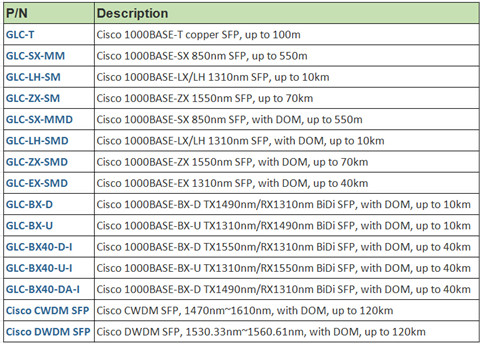
Figure 4 shows available Cisco SFPs for Catalyst 4500-X Series Switch
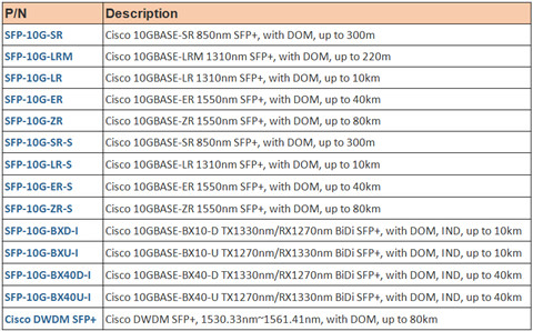
Figure 5 shows available Cisco SFP+ for Catalyst 4500-X Series Switch
Fiber Optic Patch Cables
Fiber Patch Cable, also known as fiber jumper or fiber optic patch cord is designed to interconnect or cross connect fiber networks within structured cabling systems. According to fiber cable mode, cable structure or connector types etc., fiber patch cable can be divided into different types. But remember that your fiber patch cables should always be compliant with the existing optical transceivers. For instance, LC LC multimode patch cord can be only used on the multimode optical transceivers (1000BASE-SR SFP or 10GBASE-SR SFP+). If you know nothing about this, it is advisable for you to talk with your supplier.
SFP+ Cables
SFP+ cables is the cost-effective solution for users in telecom field. It usually comes in DAC and AOC cable types. This fiber optical solution is suitable for short link applications within racks and across adjacent racks. Compared with the optical transceivers based system, it is inexpensive and more convenient. The available SFP+ cables are listed in the below chart.
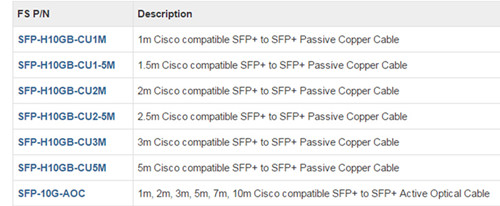
Fiberstore Fiber Optic Transceivers & Fiber Patch Cable Solutions
To sum up, in order to find the perfect fiber optic solution for your network, firstly you need to understand your needs, and consult with your vendors, then purchase all the available equipment within the budget. All the above optical devices like the copper cable, fiber optic cables, SFP & SFP+, and SFP+ DAC cables are provided at Fiberstore.
Posted by: angelina at
03:26 AM
| No Comments
| Add Comment
Post contains 952 words, total size 9 kb.
December 06, 2016
It is no secret that the technology is continually evolving, so does the demand for consistent and accessible information and entertainment. From the old 56 kbqs crawl of dial-up, to the early 1 Mbqs copper connections and all the way to the existing popular 1 Gbqs, 10 Gbqs/40 Gbqs fiber optic connections, we’ve gone through a drastic improvement to maintain a stronger signal, a better connection, a faster speed. It seems that the intricacies of internet can get complicated, so how do you draw the line with your internet consumption and speed demands? So in this blog post, we explain how fiber optic works, why cause the boom in fiber optic speed and how fast fiber optic internet can be.
How Does an Fiber Glass Function in the Internet?
We know that fiber optic cable works like a bridge between the consumer and internet supplier. But how does this process actually work? To put it simply, fiber cable works by sending data as pulses of light through a glass fiber. At one end of the fiber, a laser or LED transmits data as light. At the other end of the cable, the light will be interpreted into data by the light-sensitive receptors.
If the above explanation is not clear to you, then here comes the more vivid description. Fiber optic cables consists of a strand of fiber glass wrapped in a protective jacket called cladding. Owing to the total internal reflection, light can go from one end of the core to the other end without ever changing its wavelength. More detailed information, please see an article entitled "A Quick Lesson In Fiber Opticsâ€.
Fiber Optic Cable Types: Single-mode and Multimode Fiber
Single-mode and multimode fibers are the two broad categories of fiber core that can affect how light can travel through the cable. In single-mode fiber optic system, there is only one pathway or mode that light can travel along. While in multimode fiber optic system, seen in the below image, there are multiple pathways just like a circus funhouse with beams of light traveling along a variety of pathways through the core.
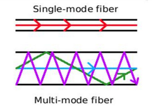
Theoretical, if you have one light beam traveling in both the single-mode and multimode fibers, the straight line beam of the single-mode fibers will reach its destination first. This difference is usually caused by the modal dispersion, which explain the reason why we often use the single-mode fibers for longer reach application.
WDM and Dark Fibers
The advent of WDM (wavelength division multiplexing) in the mod-2000s as a great breakthrough in fiber optics as it allows multiple channels to be carried at the same tine on a single fiber optic cable. There are all together CWDM and DWDM systems, CWDM or course WDM is the initial implement that allows 4 and 8 wavelengths, such as the Ethernet LX-4 standard which allowed a cable to carry four 3.125 Gbit/s data channels, resulting in 10Gbit/s aggregate.
In DWDM (Dense WDM) system, even though it is much more expensive, it can handle up to 160 data channels expanding basic a 10 Gbit/s system over a single fiber pair to over 1.6 Tbit/s.
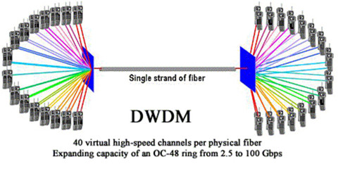
Figure 2 display different wavelengths can be bundled together in the same mode.
In terms of the new concept—dark fiber, it represents the unused cable laid in the network as space capacity, carrying high amounts of data at high speeds over hundreds of miles. Simply put, with DWDM, dark fiber network can easily increase bandwidth and allow more data to be send via optical fibers. And as the price reduces, dark fibers are gradually becoming more popular than ever.
How Do You Find out What Speed You Need?
This seems to be a noob question. As you can simply use the speed testing websites to discover the speed of your internet connection. And tracking the aspects of your internet use can give a better ideal of what speed you have and the speed that is optimal for you. What I want to express here is the common mistakes you will make.
It is not always the ISP’s fault, if your speeds are slower than what you expect. Several factors might have great impact on the accuracy of speeds. For example, the types of the hardware you have, the age/types of the line you have, and how busy the internet is at all time.
To find what speed you need depends on several different elements. How you plan to use the Internet, how many devices you have in your home, and how fast you expect to be connected are just a few factors that influence which speed is right for you. For office network, network speed under gigabit Ethernet is not sufficient.
Remember, speed is a maximum level, not a guaranteed one. As your desire for a faster connection increases, be sure you have the Internet speed that will exceed your technological needs!
The Next Steps for Fiber Optics
The modern commercial fiber optic system enjoys it stay in the Gigabit Ethernet speed. But we can look forward to the increases in the range of gigabits per second down speed, perhaps even breaking into the terabit range, in the not so distant future.
Posted by: angelina at
02:25 AM
| No Comments
| Add Comment
Post contains 875 words, total size 6 kb.
November 30, 2016
Owing to its low cost and ease of use, cables ties are ubiquitous in a wide range of telecom applications. Generally, cable ties, zip ties, or tie wraps are designed to hold items together, primarily the electric cables or wires. It is treated as a type of fastener. There are multiple types of cable ties available on the market today, such as nylon cable ties, Stainless Steel cable ties, and Velcro cable ties, etc. And each of them has their own features. So this article will introduce three common cable ties for you to select which cable ties suitable for the wire management.
Nylon Cable Ties
The common zip ties, normally made of nylon, has a flexible tap section with teeth that engage with a pawl in the head to form a ratchet so that as the free end of the tape section is pulled the tie-wrap tightens and does not come undone. The Nylon material possesses an outstanding balance of properties, combined strength, moderate stiffness, high service temperature, and a high level of toughness.
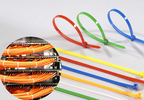
Nylon cable ties are particularly resistant to repeated impact. They have a low coefficient of friction, and excellent abrasion resistance. But they should be stored in cool dry areas, out of direct sunlight, and sealed in the original packaging material. These measures will extend cable tie performance levels indefinitely. Nylon cable ties can be broadly divided into several cable ties: Colored Cable Ties, ID Marker Ties, Eyelet Cable Ties, and Releasable Cable Ties. An article entitled "Nylon, Velcro and Stainless Steel Cable Ties†has provided some detailed information about these cable ties.
Velcro Cable Ties
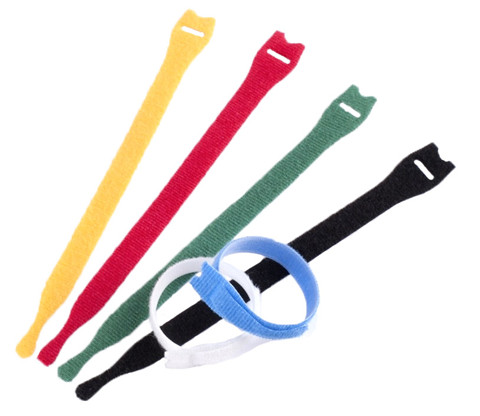
Velcro Cable Ties is made of soft hook and loop material, also known as hook and loop cable ties. They deliver reliability by protecting against over-tension of high-performance fiber and copper cables. These ties are adjustable, releasable, and reusable to effectively support frequent moves, adds, and changes (MACs). Moreover, a wide range of designs, sizes and colors provide flexibility and an aesthetically pleasing appearance. The key benefits of velcro cable ties are reliability, scalability and aesthetics. Velcro cable ties are very useful for computer and other data-cables as they will not crush the cables and cause damage.
Stainless Steel Cable Ties
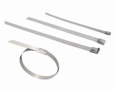
The stainless steel cable ties either naked or coated with a rugged plastic, cater for exterior application and hazardous environments. This type of cable ties are made of stainless steel, which makes them much stronger and able to achieve a tensile strength of up to 400 pounds or more. Differ from plastic cable ties, you don’t need to pull this cable tie to a tight close but through a through a self-locking mechanism. This mechanism can stand alone or be part of a ball lock system. What this locking mechanism does is add strength to the tie and ensure that it doesn’t wear down or corrode when the temperatures get too hot or cold. The best part about this locking device is that you don’t need much strength to feed the tie through. Stainless steel cable ties are ideal for applications that require a high-level of protection against corrosion and environmental conditions, which may cause typical nylon cable ties to disintegrate.
At the end of this article, one misunderstanding about cable ties needs to be explained. Cable ties, especially the plastic cable ties are generally viewed as single-use devices; they are typically cut off rather than loosened and reused. However, if a closed loop needs to be opened again, rather than destroying the cable tie by cutting, it may be possible to release the ratchet from the rack. While some cable ties are designed for reuse with a tab that releases the ratchet, in most cases a sewing needle or similar object will need to be interposed between the ratchet and the rack. Ties reused in this way will be weaker than new ones.
Posted by: angelina at
09:32 AM
| No Comments
| Add Comment
Post contains 650 words, total size 5 kb.
November 25, 2016
As the request for greater bandwidth and higher-density fiber optic connections within data centers continues, these requirements must be met by choosing the right type of connectivity. MPO/MTP fiber cable is specially designed for applications for all networking and device needs like 40G modules. It uses a high-density multi-fiber connector system built around precision molded MT ferrule, which are available in UPC and APC polish. It supports both multimode and single-mode applications, and optional lengths available. There are two main MTP/MPO cables types: MPO/MTP trunk cables and MPO/MTP harnesses cables. The following article will have a brief introduction to them individually.
MPO/MTP Standard Trunk Cables
Available in 12, 24, 48 and 72 fibers, MPO/MTP trunk cables work as a permanent link that connects MPO/MTP modules to each other. These cables are used to facilitate rapid deployment of high density backbone cabling in data centers and other high fiber environments reducing network installation or reconfiguration. A 72-fiber MPO/MTP trunk cable (see in the below image) can be terminated with 6 MPO/MTP connectors which are manufactured specifically for multi-fiber loose tube or ribbon cable. The MPO/MTP Trunk cable is designed for Data Center Applications.
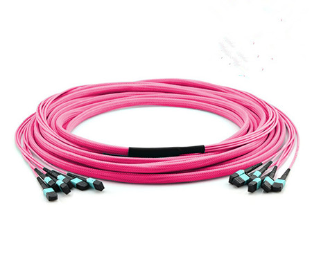
These cables can interconnect cassettes, panels or ruggedized MPO fan-outs, allowing for the flexibility in case any decision is made to change the connector style in the patch panels, new cassettes can be installed with the new connector style on the cross-connect side of the patch panel without having to change the connector on the cable trunk.
FS.COM offer single-mode (OS2) and multimode (10G OM3, 10G OM4) MPO/MTP Cable. Single-mode MPO/MTP cable is primarily used for applications involving extensive distances, 10G MPO/MTP cable provide 10G data transfer speeds in high bandwidth applications and they are 5 times faster than standard 50um fiber cable. Work with both VCSEL laser and LED sources, that means, the MTP/MPO trunk cables also provide 40G/100G MPO/MTP trunk cable.
MPO/MTP Harnesses Cables
The MPO/MTP Harnesses cable is MPO/MTP on one end, with single-fiber connectors on another end, single-fiber connector interface available in SC, ST, LC, MTRJ in forms of simplex or duplex channeling. It provides a reliable, cost-effective cabling system for migrating from legacy 10G to higher speed 40G/100GbE. They are suitable for many device needs like 100G modules, including CFP, CFP2 and CFP4 series. MPO/MTP Harnesses cable are available in SM (OS2), MM (OM3/OM4). You could select the suitable fiber according to your own needs with the selection of 12/24/72 fiber cores. The following picture shows the OS2 Fiber Optic Harness Cable.
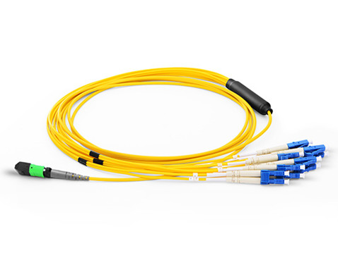
The MPO/MTP harnesses cable application for data centers requiring quick infrastructure deployment with extended reach that want to maintain bandwidth throughout the infrastructure, its design cater for up-scaling needs and future technologies growth, it’s the best solution, which covers all fiber optic cabling needs in all areas of Data Center.
High-density MTP/MPO Cables for 40G Connection
IEEE 802.3ba 40 Ethernet Standard was ratified in June 2010. This standard specifies MPO connectors for standard-length MMF connectivity. MMF employs parallel optics using MPO interconnects for 40GbE transmission. More specifically, 40G is implemented using eight of the twelve fibers in a MPO connector. Four of these eight fibers are used to transmit while the other four are used to receive. Each Tx/Rx pair is operating at 10G.
Figure 1 shows a Type B MTP female trunk cables for 40GBASE SR4 QSFP+ and multi-fiber migration networks.
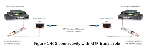
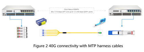
Figure 2 shows how to extend your Cisco Nexus 10GBASE-LR networks up to 40G with MTP cable and 4x10GBASE-LR SFP+ transceiver for your high speed data center solution. The 4x 10GBASE-LR SFP+ transceivers interconnection with 1x 40GBASE-LR QSFP+ transceivers (QSFP-40GE-LR4) by one MTP to 4LC harness cable directly.
Fiberstore MPO-based fiber cabling solutions provide a fast, simple and economical way for 40G applications. Certainly, 40G fiber cabling solutions are not only limited to MPO/MTP fiber cables. QSFP cables, especially direct attach copper cables are also recommended. 40G direct attach cable provides a cost-effective solution for high-density network connectivity. You can see the detailed information in an article entitled "40G Direct Attach Cable (DAC) Cables Overviewâ€.
Conclusion
To sum up, MPO/MTP cabling have proven to be an excellent solution for delivering 10G, 40G and 100G transmission, especially within a data center environment. It provides a flexible, high density option for quickly connecting services.
Posted by: angelina at
07:14 AM
| No Comments
| Add Comment
Post contains 722 words, total size 6 kb.
November 23, 2016
We know that stress and overstrain is a major enemy of the fiber’s lifespan, so cable installers must ensure that during the installation, fiber cables would not suffer from undesirable stretching or bending. Pulling, pushing and blowing are the three techniques used in wire management, which usually cause minor installation strains even for a seasoned installer. It is unavoidable, but fiber optic cables made of glasses have a limitation of bending ratio or tight diameter. If it do not exceed the certain diameter, the fiber will function well. Therefore it is essential for us to know how far cables can be bent. In fact, the maximum transmission distance of the fiber optic cable depends on the aspects like bend radius, tensile strength and usable duct space, which will be clearer illustrated in the following article.
Bend Radius
Bend radius is the curvature an optical fiber can bend without damage or shortening its lifespan via kinking. The smaller the rated bend radius, the more flexible the fiber. Just check the manufacturer’s spec for bend radius before purchasing the products. If no recommendations are available from the cable manufacturer, the cable should not be pulled into a bend radius smaller than twenty times the cable diameter. For example, a cable with an outer diameter of 5 mm, should not be bent smaller than 100mm radius during installation.
Maintaining proper bend radius is key in preventing service calls due to damage and signal loss in your optical fiber. Bend loss usually occurs when the fiber cable bends is tighter than the cable’s maximum bend tolerance, which might damage the fiber by causing micro cracks.
There are a couple of factors that may mitigate the problems of bend radius and the angles within them. If a fiber cable is being pulled or pushed through an empty duct or mini-duct, obviously there is less resistance to the cable and you can pull/push greater distances. If the coating of the outside of the cable and the inside of the duct are designed to reduce friction, you will be able to achieve greater distances as well.
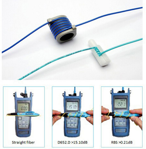
With well-designed bend insensitive fiber patch cables (seen in the above image), you can usually push a fiber cable as far as 90 degree angles in the run with minimized signal loss compared with the traditional fiber patch cables.
Tensile Strength
Just as the bend radius, fiber optic cables also have a maximum tensile strength. If the cable is being pulled through, it is better not to exceed the maximum tensile load. However, if the cable is being installed within a microduct or conduit, pushing the cable will apply no tensile force.
Over-stressing the fibers will not be noticeable until after installation since the cable outer sheath will elongate, whereas glass optical fiber will not. Ideally, a breakaway swivel should be used, however, where this is not possible, the installation crews should use a tension gauge attached to the pull-cord. As a rough approximation, 100 Newtons is equivalent to a 22lbf (pounds-force) load applied directly to the cable.
Usable Duct Space
The full space in the duct is not usable for cables because of horizontal and vertical bends and joints. Usable duct space should be at least 60%. 900µm and 250µm fibers are basically two kinds of fiber patch cables. 900µm fibers can easily be damaged with respect to the storage and wire management. 900 µm kinks easily, but is very flexible and installs easily. Sometimes, you have to balance ease of installation with toughness. The difference between 250um Loose-tube and 900um Tight Buffered Fiber have illustrated in the above article.
During the cable installation, you must get the fiber through walls—possibly in basements, attics, or crawl spaces, and then through floors, walls and, eventually, through a room to the CPE location. For rugged spaces where your fiber may suffer damage, such as basements or in conduits sharing space with electrical or other wiring, you may need a 3mm rugged sheathed cable that is flexible and crush resistant. The image below shows fiber optic cables being kinked. The flat cat5e cables (left) and common Ethernet cable (right) have different effect after bending.

Therefore, a good rule of thumb to use in planning your fiber drop is below: Bends (angles) = Friction—maximum distance of the pushable fiber
In addition to the above bend radius, here are some other areas to focus on to achieve maximum distance without damaging the cable: signal power and performance requirements for each device or revenue generating unit, locations of required splices, list of cable lengths required. When using duct or cable in conduit, keep in mind that freezing water in the conduit can crush the cable—and it may be wise to use microduct.
Summary
One of the challenges of installing fiber is to choose a cable with a very small bend radius, and it is tough enough to handle many different installation conditions. Once you have selected the appropriate fiber, plan your route to minimize bends and friction. By planning ahead and thinking carefully, you can save money by reducing the costs of those services.
Posted by: angelina at
03:24 AM
| No Comments
| Add Comment
Post contains 855 words, total size 6 kb.
November 17, 2016
People know much about the coaxial cables, but they know little about the different impedance of coaxial cables, namely 50 Ohm and 75 Ohm coaxial cables. Even many optical manufacturers fail to adequately explain the difference between the two types of coax and why they need one type over the other. Therefore, today’s article will define some of the most critical concepts regarding coaxial cable technology, and shed light on the difference between these two coaxial types.
What’s Ohm?
An Ohm is the unit of resistance used to measure the flow of electrical current through a circuit. In the most basic applications where we are dealing with DC or Direct Current electricity, we are measuring the resistance in Ohms. It is known that the smaller the Ohm, the better the performance. So a 50 Ohm cable provides much better results than a 75 Ohm cable. However, you can find the 75 Ohm cables are everywhere inside your home from the back of the TV to cable & satellite TV boxes and internet routers. Why does the 75 Ohm coaxial cables have the poor impedance but still win large popularity in the home network? In fact, there really is no good or bad impedance, just the right impedance for your application. For the detailed information about these two types of coaxial cables, please read on.
Shedding Light on Coaxial Cable
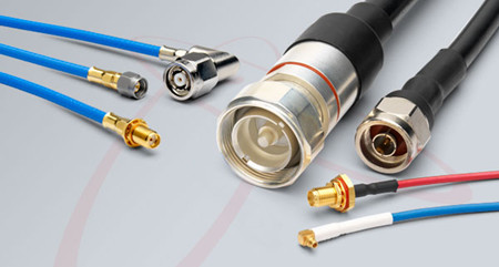
Coaxial cable, as one type of the bulk fiber optic cable, is comprised of three main components—center conductor, dielectric and shield. Center conductor as the name implies, is in the middle of the coaxial cable that can be made of either solid or stranded wire. Surrounding the center conductor is something called the dielectric. The dielectric acts as a buffer of sorts to keep the center conductor isolated and straight. Finally, on the outside of the dielectric is the coaxial cable’s shield, which is usually a combination of Copper and Aluminum foil and/or wire braid. The shield is then coated by something like PVC to insulate it from the environment. As noted before, coaxial cable can be divided into two types according to different impedance: 50 Ohm and 75 Ohm.
50 Ohm Coaxial Cables: The Forgotten Impedance
First, let’s look at 50 Ohm Coaxial Cables. Experimentation in the early 20th century determined that the best power handling capability could be achieved by using 30 Ohm Coaxial Cable, whereas the lowest signal attenuation (LOSS) could be achieved by using 77 Ohm Coaxial Cable. However, there are few dielectric materials suitable for use in a coaxial cable to support 30 Ohm impedance. Thus, 50 Ohm Coaxial Cable was selected as the ideal compromise; offering high power handling AND low attenuation characteristics.
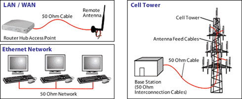
With 50 Ohm coaxial cables being the best compromise solution, practically any application that demands high power handling capacity, i.e. 100 watts or more, will use 50 Ohm Coaxial Cable. A good rule of thumb is that any device that functions as a transmitter or transceiver tends to use 50 Ohm Coaxial Cable. This includes devices such as CB/Ham Radios, Broadcast Radio/TV Transmitters, Wi-Fi and Cellular Phone Repeaters and 2-Way Radios seen in the below image. And since 50 Ohm cables aren't as ubiquitous as 75 Ohm cables in the home network, running cable is potentially more difficult if your building is not pre-wired for it. Seriously, the cable is noticeable bigger than a 75 Ohm.
75 Ohm Coaxial Cable is the Way to Go
However, not every case warrants high power handling, so 50 Ohm Coaxial Cable is not appropriate for every application. When the objective is to ensure that the signal gets through the cable in the most efficient way possible, losing very little signal strength in the process, 75 Ohm Coaxial Cable is the way to go. This includes devices such as Satellite and Cable TV Receiver Boxes, High Definition Televisions, AM/FM Radio Receivers and Police Scanners as you can see in the following image.
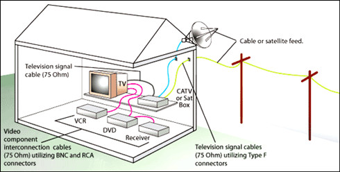
With the features of low attenuation and capacitance effectively, 75 Ohm coaxial cable becomes the cable of choice for practically all types of digital audio, digital video and data signals. This is also the reason why every cable TV company uses 75 Ohm coax for distributing its digital video channels as well as its broadband internet data signals. Additionally, direct broadcast satellite dishes and over-the-air HDTV antennas require 75 Ohm Coaxial Cable to ensure that all of the digital channels transfer down the cable with the lowest loss and distortion possible.
75 Ohm cables are the standard coax cable and they're commonly used and are often pre-wired in many homes and businesses. In all, 75 Ohm is primary used for video and audio, hence why it's rapid adoption.
Conclusion
To sum up, the 75 Ohm cable is the primarily utilized for the transmission of a video signal. In the case of 50 Ohm cable, it is a data signal that is for the most part being transmitted. To put it simply, 75 Ohm is for pictures and 50 Ohm is for information.
Posted by: angelina at
03:29 AM
| No Comments
| Add Comment
Post contains 847 words, total size 6 kb.
November 11, 2016
Questions like whether a 1G SFP can be used on the SFP+ port of the switch and support 10G data rate are frequently asked by overall users. Generally, you will get the answer "noâ€. Because Most (95+%) SFPs and SFP+s will only run at the rated speed, no more, no less. Even though SFP and SFP+ have the same port size, it doesn’t mean that you can insert a SFP in a SFP+ port to achieve a 10G connectivity. Not to mention that some SFP+ port can only support 10G SFP+ optics. However, this article will introduce a Cisco Network module in Cisco Catalyst 3750-X and 3650-X Series switches that can both support 1 GbE SFP and 10 GbE SFP+ transceivers.
C3KX-NM-10G Network Module
The Cisco Catalyst 3750-X and 3560-X series switches support four optional network modules for uplink ports, namely C3KX-NM-1G (four GbE port network module), C3KX-NM-10G (two 10GbE SFP+ ports network module with four physical ports with two SFP+ and two regular SFP ports), C3KX-NM-10GT (two 10GB-T ports network module), C3KX-SM-10G (service module with two 10GbE SFP+ ports network module for Netflow and MACsec encryption). C3KX-NM-10G module on the Cisco Catalyst 3750-X and 3560-X has two installation screws on each side, which make it easy to switch things out and make new connection without a fuss. What’s more, when business demands changes, the C3KX-NM-10G network module allows customers to only upgrade their modules from 1 GbE to 10 GbE without replacing a comprehensive upgrade of switch.
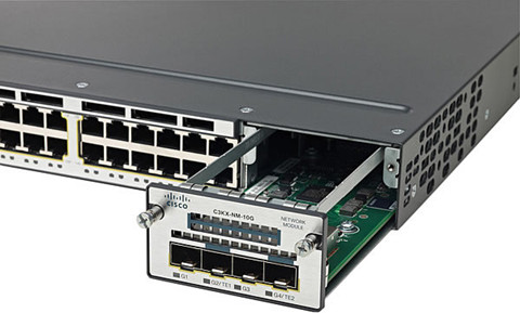
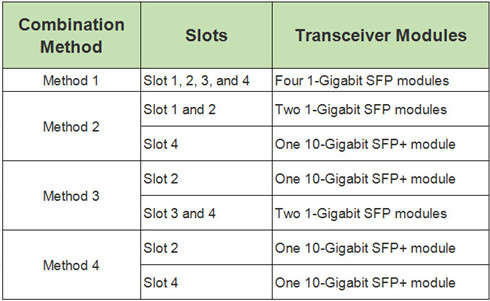
As the above image shows, the C3KX-NM-10G network module has four slots—two SFP+ slots and two SFP slots. These four slots usually work in pair, with one pair supporting 1 GbE data rate and the other achieving 10 GbE. Note that you must use the same form factor transceiver in a pair and never mix the SFP module with SFP+ module. SFP+ can’t auto-negotiate down to 1G to support with SFP module.
To put it simply, let’s name the port from left to right as slot 1, slot 2, slot 3, slot 4. Usually a 10-Gigabit SFP+ module takes precedence over a 1-Gigabit SFP module. But it’s another case when an SFP module is first inserted in Slot 1 and has link. For example, if the SFP in Slot 1 retains link, you insert an SFP+ module in Slot 2 and it will not operate. If the SFP module in Slot 1 is shut down or removed, the SFP+ module in Slot 2 turns on. The SFP module in Slot 1 does not work as long as an SFP+ module is in Slot 2. The following chart concludes the accessible combination of SFP and SFP+ modules.
Suitable Cisco Transceivers for C3KX-NM-10G Network Module
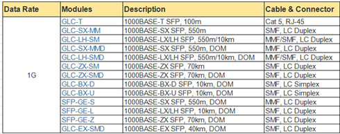
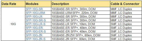
As note before, C3KX-NM-10G module on the Cisco Catalyst 3750-X or 3560-X series switch can both support 1 Gigabit Ethernet and 10 Gigabit Ethernet data links. We will list the available Cisco modules attached with detailed information in the below charts.
Cisco SFP transceiver for C3KX-NM-10G module:
Cisco SFP+ transceiver for C3KX-NM-10G module:
Conclusion
This post lists all of the functions of the Cisco C3KX-NM-10G network module, all the basic and advanced features and tells you how to select the compliant Cisco SFP modules and SFP+ modules. If you want to expand your database from 1GbE to 10GbE, with the Cisco C3KX-NM-10G network module, you only need to upgrade your Cisco SFP and plug it with a brand new SFP+ transceiver, then that’s it.
Posted by: angelina at
06:58 AM
| No Comments
| Add Comment
Post contains 579 words, total size 5 kb.
November 09, 2016
Fiber optic attenuators are often used to control the optical signal strength in fiber optic links. For example, in a DWDM based system, the DWDM employs multiple wavelengths and channels in different communication protocols and bit rates requiring precise tuning of the power levels of the channel signals. Fiber optic attenuators are often used to adjust the optical power signal strength. How exactly does the fiber optic attenuator work? This article might provide you some information.
What Is Fiber Optic Attenuator?
A fiber optic attenuator, also called as an optical attenuator, can simulate the optical loss that could be caused by a long period of fiber. Put it simply, for a fiber optic receiver, too much light can overload it and degrade the bit error ratio. Therefore, the light power at the receiver end should be reduced. Fiber optic attenuators fit the requirement perfectly. This usually happen when the transmitter delivers too much power like the single-mode system, or the transmitter is simply too near to the receiver. Optical attenuators can be divided into two types—fixed and variable attenuators.
Fixed Fiber Optic Attenuators
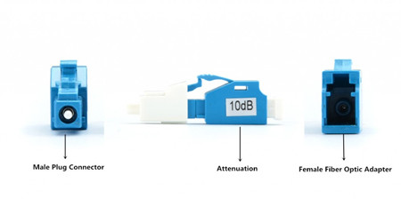
Fixed fiber optic attenuator, also called fixed plug type or fixed build-out fiber optic attenuator, is used in fiber optic communications to reduce the optical fiber power by a certain level. Fixed fiber optic attenuators have fixed values that are specified in decibels from 1dB to 30dB. Usually, it has a male plug connector at one side to allow the attenuator to be plugged directly into receiver equipment or adapters in patch panel, and has female type fiber optic adapter at the other side to allow the patch cords to plug in (seen in the below image).
Fixed fiber optic attenuator is based on the connector type and the attenuation level. For instance, LC 10dB fixed fiber optic attenuator means this attenuator use LC fiber optic connector, and it can reduce the optical fiber power level by 10dB. Their applications include telecommunication networks, optical fiber test facility, LAN and CATV systems.
Variable Fiber Optic Attenuators
Variable fiber optic attenuators (or adjustable fiber optic attenuator) are with adjustable attenuation range. It usually is inline type, the appearance like fiber optic patch cord; it is with an adjustable component in the middle of the device to change the attenuation level to a certain figure. There are also handheld variable fiber optic attenuators; they are used as test equipment, and we have the inline fiber optic attenuators.
How to Use Fixed Fiber Optic Attenuator?
In general, multimode systems do not need attenuators as the multimode sources, VCSELs, rarely have enough power output to saturate receivers. Instead, single-mode systems, especially short links, often have too much power and need optical attenuators. Therefore, fixed fiber optic attenuators are usually single-mode types. Fixed fiber optic attenuators should be always installed at the receiver end of the link (X in the drawing). This is because it’s more convenient to test the receiver power before and after attenuation or while adjusting it with your power meter at the receiver, plus any reflectance will be attenuated on its path back to the source.
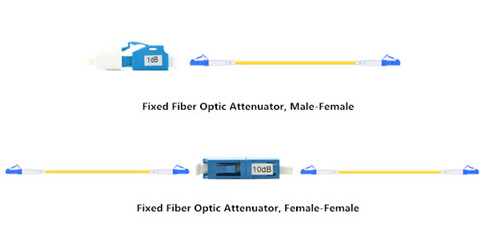
For female to male fixed fiber optic attenuators, we can plug the fiber cable to the female fiber optic adapter of the attenuator. And then plug the male plug connector of the attenuator to the equipment directly. For female to female fixed fiber optic attenuators, we should plug the two patch cords to the two female fiber optic adapter of the attenuator (shown in the above figure).
Posted by: angelina at
03:24 AM
| No Comments
| Add Comment
Post contains 589 words, total size 5 kb.
November 02, 2016
Do you have the experience of setting up a fiber switch for your network system? Or do you feel distressed for choosing an ideal fiber switch for you clients? Fiber switch is the dispensable telecom device that joins multiple devices within one network. There are many factors to be considered before you make a product choice. One of the key points is that fiber switch must accommodate severs and storage devices both for the present and future proof. Today’s article has concluded the frequently asked questions about selecting a fiber switch, and provide some assistance to you.
Fiber Switch Overview
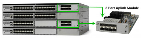
Before we come to the main part, let’s have a brief overview of the fiber switches. Generally, fiber switch is broadly divided into two main category—modular and fixed configuration. The modular fiber switch just like the Cisco 4500 series switch (seen in the below image), allows you to add expansion modules into switched as needed, thereby delivering the best flexibility to address changing networks.
While the fixed configuration fiber switch, as the name implies, are switches with fixed number of ports and are typically not expandable. Cisco Catalyst 3750 is the good example of this. The fixed configuration switch category is further broken down into: unmanaged switch, smart switch and managed L2 and L3 switch. Each of them can be used in different situation.
How to Choose a Fiber Switch?
In the previous article entitled "Why Choose to Use a Managed Ethernet Switch?â€, it mentioned the reasons why people should use managed switch other than unmamaged switch. Mangaed switch can give you better control over LAN traffic and offer advanced features like remote management, Redundancy, QoS services. Besides the above factors, some common features about choosing a right fiber switch is listed below.
Transmission Speed
Fiber switches are typically in Fast Ethernet, Gigabit Ethernet, 10 Gigabit and even 40/100 Gbps speeds. These switches have a number of uplink ports and downlink ports. Downlinks connect to end users, and uplinks connect to other Switches or to the network infrastructure. Currently, Gigabit speed is the most popular interface speed though Fast Ethernet is still widely used, especially in price-sensitive environments. 10 Gigabit has been growing rapidly, especially in the data center and, as the cost comes down, it will continue to expand into more network applications. And the 40G/100G is still emerging and will be mainstream in a few years. For example, the commonly used Catalyst 3750 is armed with 48 Ethernet 10/100/1000 ports with IEEE 802.3af PoE and 4 SFP uplinks, which is suitable for 1G application.
Number of Ports
Fiber switches typically come in 5, 8, 10, 16, 24, 28, 48, and 52-port configurations. These ports may be a combination of SFP/SFP+ slots for fiber connectivity, but more commonly they are copper ports with RJ-45 connectors on the front, allowing for distances up to 100 meters.
PoE Versus Non-PoE
Power over Ethernet (PoE) is a capability that facilitates powering a device (such as an IP phone, IP Surveillance Camera, or Wireless Access Point) over the same cable as the data traffic. One of the advantages of PoE is the flexibility it provides in allowing you to easily place endpoints anywhere in the business, even places where it might be difficult to run a power outlet.
However, switches have a power budget set aside for running the switch itself, and also an amount of power dedicated for PoE endpoints. For example, PoE switches according to 802.3af standard deliver power up to 15.4 Watts on a switch port, and IEEE 802.3at (also known as PoE+) delivers power up to 30 Watts on a switch port. For most endpoints, 802.3af is sufficient but there are devices, such as Video phones or Access Points with multiple radios, which have higher power needs. It’s important to point out that there are other PoE standards currently being developed that will deliver even high levels of power for future applications.
Whether to choose a PoE switch or non-PoE switch, you need to consider the features associated with the PoE capacity as well as your power needs. When connecting to desktops or other types of devices which do not require PoE, the non-PoE switches are a more cost-effective option.
Conclusion
When you are preparing a new installation with Fiber running, choose a suitable switch is essential. But if you search on the internet, you will find there are many types of switches on the market. Take Cisco as an example, it had launched a series of switches, and each has different performance. I hope this article can provide you some steep learning curve about fiber switches. It is advisable for you to ask an expert for help, or you may waste your money.
Posted by: angelina at
07:42 AM
| No Comments
| Add Comment
Post contains 789 words, total size 6 kb.
October 26, 2016
Although the 40G/100G optical modules are on the very top trend for enterprise and data center for the interconnection, 10G transceiver modules are still in great demand. There are several types of 10G optical transceiver modules available for sale including the XENPAK, X2, XFP, small form-factor pluggable plus (SFP+) transceiver, of which 10g SFP transceiver (due to its small size and low power) is the most popular type for 10G network. According to the 10 Gigabit Ethernet standard, SFP+ transceiver can be classified into many categories: 10GBASE-SR SFP+, 10GBASE-LR SFP+, 10GBASE-ER SFP+, and 10GBASE-LRM SFP+. This article will focus on the introduction of the 10GBASE-LR SFP+ and 10GBASE-LRM SFP+ transceivers.
10GBASE-LR SFP+
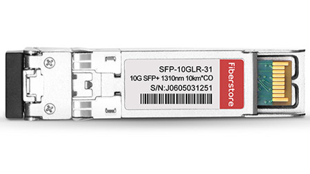
10GBase-LR can support up to 10km over single-mode fiber and uses 1310nm lasers. There is no minimum distance for LR, either, therefore it is suitable for short connections over single mode fiber too. The Cisco 10GBASE-LR module supports a link length of 10 kilometers on standard single-mode fiber (SMF, G.652). FS.COM compatible 10GBASE-LR SFP+ transceiver possesses the same function as the original one with a much lower price than Amazon and ebay. The following image shows a Cisco Compatible SFP-10G-LR SFP+.
10GBASE-LRM SFP+
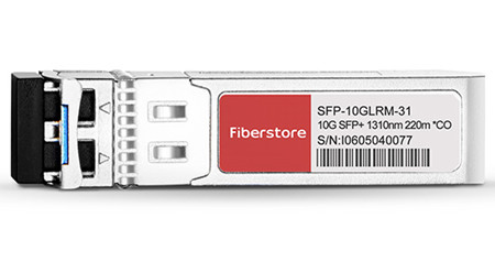
10GBASE-LRM still uses the 1310nm lasers, but it can only reach up to 220m over standard multimode fibers. The 10GBASE-LRM can be packaged in XFP and SFP+ form factors. FS.COM Cisco SFP-10G-LRM Compatible 10GBASE-LRM SFP+ supports link lengths of 220m on standard Fiber Distributed Data Interface (FDDI) grade multimode fiber (OM3/OM4). The following image shows a Cisco Compatible SFP-10G-LRM SFP+.
Besides the Cisco SFP-10G-LRM, there are a new type of the 10G SFP+ module for multimode fibers—SFP-10G-LRM2. It is a type of SFP+ transceivers compatible with the 10GBASE-LRM standard. SFP-10G-LRM2 can reach up to 2km over standard multimode fiber.
Contrast Between 10GBASE-LR and 10GBASE-LRM SFP+
At the first glimpse of the two terms—10GBase-LR and 10GBase-LRM, people usually have the misconception that they are similar with each other. In fact, 10GBase-LR and 10GBase-LRM meets different demands just as described in the above article. SFP-10G-LR optics (compatible with 10GBase-LR) supports a link length of 10km on standard single-mode fiber (SMF). SFP-10G-LRM (compatible with 10GBase-LRM) optics supports link lengths of 220m on standard Fiber Distributed Data Interface (FDDI) grade multimode fiber (MMF). When you use the OM1 or OM2 fibers connected with the 10GBase-LRM module, to make sure that specifications are met over FDDI-grade, the transmitter should be coupled through a mode conditioning patch cord. But it is fine when you use over the OM3 and OM4 fibers.
Conclusion
10G SFP+ transceiver is widely used to support communication standards including synchronous optical networking (SONET)/synchronous digital hierarchy (SDH), 10 Gigabit Ethernet and fibre channel. Both 10GBASE-LR and 10GBASE-LRM SFP+ wins its own place on the market. They cannot substitute for each other!
Posted by: angelina at
03:54 AM
| No Comments
| Add Comment
Post contains 469 words, total size 4 kb.
October 21, 2016
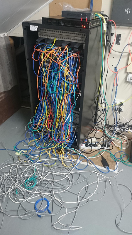
Network designers may encounter a problem when they are about to organize the spaghetti-hell cables in the rack (seen in the below image). They don't know where to start. So how do you organize the cables in your racks? What method do you use for the re-installation? Do you use any tracking software or physically label the cables? How to label the cables? In fact, it is essential for data center infrastructure to well organize all the cables in the racks. It not only helps users install and route cables in an easier and more accurate way, but reduce the time required for further maintenance. Therefore, this article will provide two identify methods to help you out.
Label Each Cable and Panel
Labeling system can clearly identify all components of the structured cabling system including racks, cables, panels and outlets. If you don't label your cables, you're only making more work for yourself. Every cable should have a label on both ends, even short runs and patch cables. Only in this way, you will know where each cable goes when you unplug a few patch cables for a switch, and reset them back to their default locations.
There are two methods that you can use to label your cables with a generic labeler. You can run the label along the cable, so that it can be read easily, or you can wrap it around the cable so that it meets itself and looks like a tag. The former is easier to read, the latter is either harder to read or uses twice as much label since you type the word twice to make sure it's read. Long labels on mine get the "along the cable" treatment, and shorter ones get the tag.
Use Color Coding for Quick Visual Identification
Color coding can be a solution to the problem of wire identification, making locating cables from a distance easier. Users should use a specific color cable for a specific purpose so that they can easily and rapidly trace cables back. And one thing you are supposed to bear in mind is that never use colors randomly. Make sure each color has a purpose and stay with it. That will make it easier to follow cable runs and troubleshoot issues. And it also makes for a better-looking data center. The below image shows the example color scheme for patch cables.
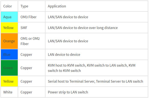
Note: the color scheme depends on the cable manufacturer and your color coding plan. If you use colors to identify cable functions or connections, be sure to build in redundancy to accommodate individuals with color blindness or color vision deficiency.
Hints About Color-Coding and Labeling
- Visually identifying cables will save you time tracking them down.
- Use color and labels to identify and organize: cables’ role and function or connection type, dual-power feeds for redundant power sources.
- Use secure labels that can be seen but difficult to remove.
- Maintain a spreadsheet that identifies the cables and colors, where cables come from and go, and configurations.
Summary
There is no need to mention the importance of cable identification. Once you begin to identify the cables in your racks (whether to use color coding or labeling), please hold on to it. Or you'll confuse yourself and those who work for you. In all, use of the color coding or labels is the best practice to identify cables in a rack.
Posted by: angelina at
03:42 AM
| No Comments
| Add Comment
Post contains 574 words, total size 4 kb.
October 19, 2016
Patch panel is undoubtedly an essential component in cabling systems as it provide a simple, neat and easy-to-manage solution. For example, if you want to wire a network system that includes multiple wall ports, patch panels will not only allow you to terminate cable elements, but the signal to be connected to the final destination. No matter how big or small your business infrastructure is, patch panel is indispensable. So what is a patch panel? What are the exact benefits of using fiber optic patch panel? This article will provide some detailed information about the benefits and challenges of them.
What Is A Patch Panel?
A patch panel is, in fact, an array of ports on one panel used to connect and manage incoming and outgoing LAN cables. The following image shows a 128 fibers MTP to LC/UPC OM4 1U 40GB QSFP+ Breakout Patch Panel. Each ports of patch panels connect fiber jumper cables to another port located elsewhere in your building. Circuits in an enterprise network can be easily rearranged by plugging and unplugging respective patch cords. Furthermore, patch panel provides a single location for all input jacks, which greatly simplifies the troubleshooting problems.
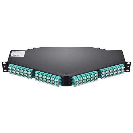
Patch panels are usually attached to network racks, either above or below network switches and take up 1U or 1.75 inches of space. Patch cords connect the ports in the patch panel to ports in the network switch, which creates permanent port connections to the switch that won't be interrupted during moves, adds and changes (MACs). Based on different standards, there are different types of patch panels. For instance, 48-port, 24-port and 12-port patch panels divided by the number of ports, or the more specific patch panels—Cat 5E, Cat 6, Cat 6A and Cat 7 cables. Since you have a basic understanding of patch panels, let’s move on the the next part.
The Benefit
A patch panel performs no other function except for acting as a connector, but it does offer a range of benefits:
- Use Standard Fiber Optic Cords
Since patch panel uses fiber optic cable to create interconnection, network designers can make changes and repairs without the delays and added expense associated with custom cabling.
- Flexibility and Scalability
The network can grow and change on-demand, without the costly, labor-intensive hassle of replacing channels end-to-end.
- Reduce Cable Congestion
Reduced cable slack means less clutter, less confusion and an easily organized, better-labeled cabling infrastructure. You can also manage cables in any direction–horizontal or vertical, front or back.
- Space Saving
By managing varying port densities and speeds in a single high-density patch panel, you save valuable rack space, helping to lower data center costs. A single patch panel can manage as many as (16 10 Gb ports.
- Cost-Effectiveness
High-density and easy maintenance provide a low initial investment cost. With a patch panel, you can only buy the devices you need now, while leaving room for future expansion.
- Ease of maintenance
The advantage of using a patch panel is that it allows manual monitoring, testing, switching, routing, and other maintenance to be handled quickly because the cables in the front that connect to the more permanent cables in the back are configured and made so that changes can be made quickly and easily when needed.
The Challenge
With several patch panels available for sale, network users usually feel puzzled to select a patch panel solution with the features and capacity to meet their current needs, as well as the flexibility and scalability to adapt to and grow with the future needs. As noted before, patch panels can be divided into several types. According to different cable type, there are copper and fiber patch panels, which will be introduced in the next part.
Copper or Fiber Patch Panel?
A Patch panel can be connected with either fiber or copper cabling. The primary role of fiber patch panel is to direct signal at a required speed. It is the common sense that fiber is much faster than copper, and fiber patch panels are more expensive.
Structurally, copper panels have the 110-insulation displacement connector style on one side and 8-pin modular ports on the other. Wires coming into the panel are therefore terminated to the insulation displacement connector. On the opposite side, the 8-pin modular connector plugs into the port which corresponds to the terminated wires. With the copper panel, each pair of wires has an independent port. The following image shows the 48 Ports Shielded(STP) Cat6 Feed-Through 2U Gigabit Ethernet Patch Panel.

Fiber panels require two ports for a pair of wires. One port serves the transmitting end while the other handles the receiving end. While fiber panels tend to be faster than copper, this does not downplay the role played by the latter. And if there are more than one type of the fiber optic connector used in the network, patch panels with hybrid adapters are necessary. These adapters can then be used to plug individual fibers into other devices. The adapters on a fiber optical patch panel can come in a variety of different shapes.
Conclusion
To sum up, the patch panels make it easy to organize the fibers in an business or home network. What’s more, working with the fibers within the tray of the fiber optical patch panel protects the fibers from anything in the environment that could damage them.
Posted by: angelina at
04:00 AM
| No Comments
| Add Comment
Post contains 892 words, total size 7 kb.
October 12, 2016
Fiber optic joints or termination is a necessary process when installing a network. Every network operators who aim to deploy a next-generation fiber network have to determine how to build a flexible, reliable and long-lasting infrastructure at the lowest possible cost. In general, there are mainly two fiber optic termination methods: splices which create a permanent joint between the two fibers, or connectors that mate two fibers to create a temporary joint. When people decide to use either method, many factors should be taken into account. Today’s article will evaluate both methods from the aspect of cost to help you choose the effective termination method.
Weighting the Two Methods
Besides the features of low loss, minimal reflectance and high mechanical strength, fiber optic termination must be compatible to the environment in which they are installed. Before we come to the cost comparison of these two termination methods, let’s firstly have a brief overview.
Fusion splicing
As it known to all that, splices create a permanent joint between two fibers, so its use is limited to place where cables are not expected to be available for servicing in the future. The most common application for splicing is joining cables in long outside plant cable runs where the length of the run requires more than one cable. There are two types of splices, fusion and mechanical. Fusion splicing is most widely used as it provides for the lowest loss and least reflectance, as well as providing the strongest and most reliable joint.
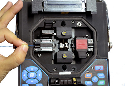
Fusion splicing machines are usually called fusion splicer available on the market that splice a single fiber or a ribbon of 12 fibers at one time. The above picture shows how to splice a fiber optic jumper. Virtually all single-mode splices are fusion. Fusion splices are made by "welding" the two fibers together usually by an electric arc. To be safe, you should not do that in an enclosed space like a manhole or an explosive atmosphere, and the equipment is too bulky for most aerial applications, so fusion splicing is usually done above ground in a truck or trailer set up for the purpose.
Today's single-mode fusion splicers are automated and you have a hard time making a bad splice as long as you cleave the fiber properly. Fusion splicers cost thousands US dollars (up to $5,000), but the splices only cost a few dollars each. The following part display the main features of the fusion splicing:
- Typical average optical losses of 0.05dB or lower
- Not de-mateable
- Special installation skills needed
- Tools sensitive to the environment
- Relatively long installation time
- Standard organizer techniques required
Pre-terminated System
Pre-termination is the alternative termination method popular on the market. Cables and fibers are terminated to a connector in the factory. When carefully planned, splicing jobs for specialized technicians can be limited to the network construction phase. But provisioning, churn and network testing can be performed by technicians without specific fiber skills, because the organizers can be very simple.
With pre-connectorized products, the connection time is reduced from 20 to less than 5 minutes, including the connector cleaning step. When connecting fibers with connector technology, there is no issue of environmental sensitivity. What’s more, connectors are accessible on the outside of the network element, reducing the need to access a product and the risk of disturbing other lines. The image below shows the MPO pre-terminated cables.
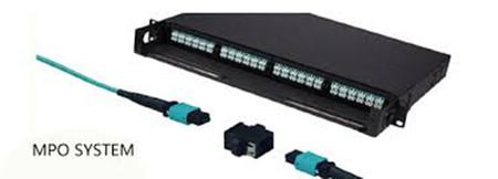
Factory pre-termination is also compatible with optical budget requirements by selecting the appropriate grade as defined by the international IEC standards. When properly planned, pre-connectorizedproducts do not add extra connectivity points, thus eliminating extra optical loss or reflections. In all, the most obvious features of the pre-terminated system lies in the following part:
- Typical losses of 0.15dB or less
- Fully de-mateable
- No special installation skills required
- Reduced installation time
- Very simple organizer systems
- Insensitive to environmental conditions
Cost Comparison
The start-up costs for the fusion splice are significantly higher, as fusion splicers can be very expensive. Even the cheapest fusion splicer will cost nearly $2,900 (FS-F600 Fusion Splicer from FS.COM) more than the most expensive crimp kit. Not counting the initial start-up costs, splices will run anywhere from $7.20 to $8.25 per splice, which is much lower than the pre-terminated connector. The following image shows the vivid comparison between fusion splicing and pre-terminated system.
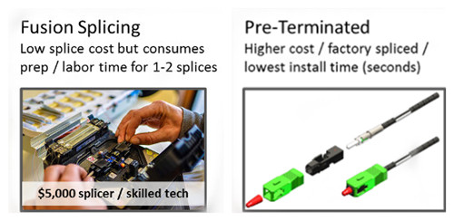
As for the pre-terminated connector, the most significant advantage is the wire management hardware involved. A pre-terminated connector requires no additional hardware over a standard connector. And it is faster to terminate a crimp connector, saving labor time ($0.75 per splice), and splicing also requires additional material costs in the form of splice protectors ($0.40 per splice). Fiber splicing technicians have specialized training that makes them expensive when compared to someone simply plugging things in. The additional material and closet space for managing splices can cost an additional $6.05-7.10 per connector. But with a little careful planning as to lengths of fibers needed, pre-terminated fibers can be installed quickly and with no training.
In all, fusion splicing makes a lot of sense for trunk fibers and locations where there are anywhere from 48 to 192 fibers to splice. In the drop locations, where there may be only one or two splices at each location, the setup time for each location may negate any cost savings from fusion splicing.
Making the Choice
In comparing pre-termination and fusion splicing, both have their inhered advantages. Fusion splicers offer many advantages in the premises environment, from being lightweight and compact to operating on a battery. These new units minimize setup time and are ideal for use in locations where space is tight. In addition, the total splice and heater cycle time is less than one minute, thereby enabling technicians to move through many termination locations quickly.
However, we cannot deny the fact that the start up cost of the fusion splicing is huge, thus customers that can’t deal with budget are going to demand pre-terminated connectors. Pre-terminated solutions offer the most benefits: It’s easy to install pret-terminated cables, and because they’re available in custom lengths, it’s easy to get the exact lengths required to limit the excess slack. Many more users will rely on the pre-terminated trunk cables and sacrifice the inconvenience of dealing with slack, because it offers faster deployment.
As you get into significantly higher fiber counts, fusion splicing could save time over installing connectors. While for those who don’t have a fusion splicer or splicing experience, may want to consider pre-terminated connectors.
Posted by: angelina at
02:41 AM
| No Comments
| Add Comment
Post contains 1085 words, total size 9 kb.
October 07, 2016
With the ever-increasing demand for more computing power and data center servers, data center manager have the responsibility to chart a data center capacity plan and determine what strategy will accommodate business needs best. Of course, they could just expand to large facilities (upgrading to the advanced switch and fiber enclosures). However, not all IT budgets are increasing, and many users just cannot afford the extra money. Therefore, people are turning to high-density and cost-effective infrastructures. To support these applications, this article will introduce a broad selection of high-density connectivity and high capacity cable management devices.
- High-Density Patch Panels
High-Density (HD) fiber patch panel solution is the most convenient approach for solving the problem of limited capacity in a data center environment. And it provides a flexible way to connect devices of different generations of equipment quickly and easily. HD patch panels consist of a panel enclosure and modular HD cassettes, which can connect a fiber network feed (via multi-strand or MTP cable) and segment it into standard LC connections in order to interface with 10Gbps devices. The following image shows a fiber adapter panel with 12 LC duplex single-mode adapters.
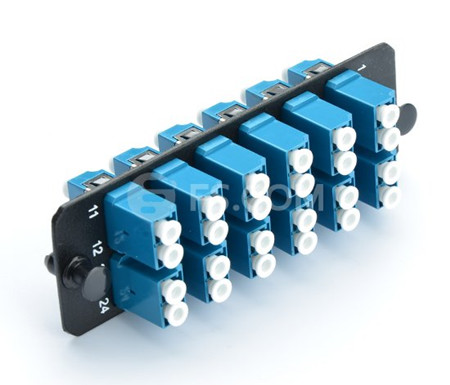
HD fiber patch panels feature the following advantages:Flexibility: They can connect different generations of equipment such as 10Gb, 40Gb, 100Gb in a simple panel-cassette system with different connector types.
Ease of Installation: No tools are required to install the cassette in the panel enclosure. Each cassette features factory terminated connectors that reduce the time and labor required of field connector terminations.
Cost-Effectiveness: High-density and ease of installation provide a low initial investment cost. Flexibility, adjustability and reliability provide a high ROI. What’s more, network reconfiguration is highly adjustable due to the modular cassette system.
- High-Density Patch Cords
As cabling density increases along with the deployment of higher network speeds, HD patch cords deliver a robust design to withstand the rigorous of daily use. Cables that can offer a smaller overall diameter improve cable management by installing in dense patch cord trays that take up less space. They also provide better airflow to maintain consistent operating temperatures, reducing the likelihood of failure or downtime.
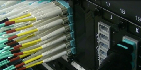
Finger access to each patch cable, furthermore hinder the cable management and makes the cable installation become more difficult. To ensure easy access, high-density patch cords are easy to remove through the use of a flexible pull-tab fiber optic cable just as seen in the above picture. This cable type has the same component and internal structure as the traditional patch cords (e.g.SC FC patch cord), except the a tab attached to the connector, which makes it easy for cable management. These tabs can help increase cabling density and maintain reliability, preventing you from accidentally loosening surrounding connectors as you access the patch cord you need.
MPO/MTP trunk cable is the another example of the HD patch cords. These cables are the foundation of easier, faster and better pre-terminated fiber connectivity solutions, as it allows tighter trunk cable bends for slack storage and routing. With the high-density trunks in your data center solution, less space is consumed and installation is easier.
- High-Density Fiber Enclosures
Fiber enclosure makes full used of the spaces in data center by combining most of the fiber optic connections in strong standards modules, providing solid protection of data center links and increasing cabling density. Therefore, data center managers can get easy access to fiber connections and easy cable management. Accordingly, the cost for data center installation and maintenance can be effectively reduced.
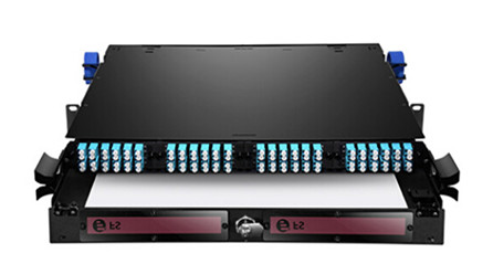
Fiber enclosures are usually available in 1U, 2U, 3U, 4U. The 1U rack mount fiber enclosure is the most commonly used one on the market. Now 4U or larger rack mount fiber enclosures are also becoming popular driven by the increasing of fiber counts in data center. Except standards rack mount fiber enclosures, a lot of data centers or server rooms use customized fiber enclosures for their special requirements.
FS.COM FHD Series rack mount fiber enclosures are available in 1RU, 2RU and 4RU rack unit options. With optional FHD cassette modules or adapter panels in single-mode, multimode, or 10G multimode versions, users can install, maintain, and upgrade their cabling systems in a more flexible and cost-effective way. In addition to rack mount solution, our FHD series products also support wall mount type which can meet the cabling demands on fiber industrial environments.
Conclusion
High-density optic solutions enable data center operators to maximize the amount of active equipment and cables in a data center by minimizing the foot print of the networking infrastructure. Besides the above HD optical products, there are also a range of HD products including the high speed interconnect optics, cable assemblies, cable management hardware.
Posted by: angelina at
02:51 AM
| No Comments
| Add Comment
Post contains 785 words, total size 7 kb.
September 21, 2016
There is no doubt that fiber optic cables play an integral role in telecommunication industry. Applications like data centers, local area networks, telecommunication networks, industrial Ethernet, and wireless network are all needing fiber optics to ensure smooth connectivity. Each application requires a specific cable design based on performance requirements, environmental conditions, and installation type. The common fiber optic cables like LC to LC patch cord cannot adapt to the harsh environment (e.g. moisture environment or underground deployment), thus water-resistant fiber optic cables are highly demanded on the market due to their water proof nature. Here is what you should know about the water-resistant fiber optic cable.
Overview of Water-resistant Fiber Optic Cables
Water-resistant fiber optic cable refers to the special type of fiber optic cable that are designed and specified for installations where the cable will come in contact with water or moisture, such as aerial, direct buried, or in conduit. The cables in these applications are exposed to or can be temporarily submerged in water, so they contain either a water-resistant gel-filled or gel-free (dry gel) polymer.
Generally, fiber optic cables can be divided into three types—outside plant cable (OSP), indoor/outdoor, and indoor, which are specified based on the environment and location where they are installed. With the exception of indoor cables, all cables contain water-resistant gel-filled or gel-free material to protect them from water and moisture. Before the use of gel-filled and gel-free materials, flooded core was another water-blocking method that is rarely used today (it has been replaced with gel-filled). The following image shows the gel-filled cables.
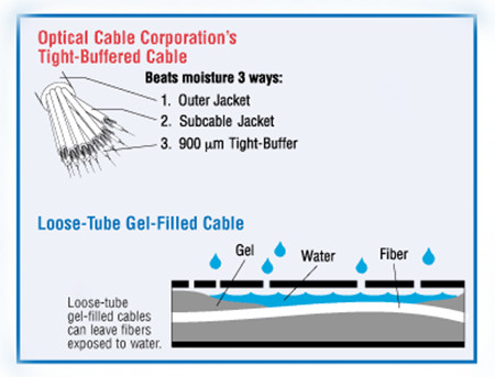
The gel is a gooey substance that must be removed when accessing and installing the cable. Gel-free cables, which are now more widely used, contain a super-absorbent polymer powder that is activated when it comes in contact with water or moisture. This blocks the water from penetrating the cable and allows for some expansion and contraction with temperature changes. Indoor cables do not contain water-resistant material since they are not typically exposed to water. Indoor (and indoor/outdoor) cables must meet additional flammability requirements dictated by local codes, such as the National Electrical Code.
Tight-Buffered & Loose Tube Cable Construction Provides Excellent Moisture Resistance
Water-resistant materials and cables are included in many industry specifications and standards. Generally, there are two basic water-resistant cable designs: Tight-buffer cables (primarily used inside buildings), Loose tube cables (used for OSP and indoor/outdoor).
It is known to all that most tight-buffered cable designs (seen in image below) are specified for indoor use, but some of them are designed with water-resistant powder and yarn, making them suitable for some indoor/outdoor applications. This tight-buffered cable utilizes an different design approach to deal with the moisture issue. Buffer materials are low-porosity plastics with excellent moisture resistance. This construction very effectively minimises the water molecule and OH-ion concentration level at the glass surface and virtually eliminates the stress corrosion phenomenon.
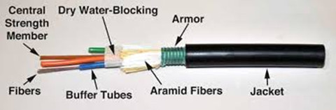
In loose tube cables (seen in image below), in order to prevent the water from reaching the 250μm coated fibers, the tubes surrounding the fibers must be filled with water-absorbent powder or gel that withstands high-moisture conditions, making them excellent for outside plant applications. This approach is especially made to waterproof the cable by filling the empty spaces in the cable with gel. The gel-filled tubes can also expand and contract with temperature changes, which makes loose-tube cable great for harsh, high-humidity environments where water or condensation can be a problem. However, gels can move, flow, and settle, leaves an uncertainty of the filled level of any particular point of a loose-tube gel-filled cable. Because loose-tube cable is typically 250 microns, you'll need a fan-out kit to build up the individual fiber strands to 900 microns when making the transition at the entrance point from outdoor loose-tube to indoor to tight-buffered cable.
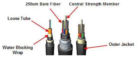
The same level of protection remains in place all along the fiber, regardless of installation conditions, environment, or time. The balance of the tight-buffered, tight bound cable designs is such that it minimizes the open spaces available in the cable structure in which water can reside. Even if an outer cable jacket is cut, or water otherwise enters the cable structure, only a very small percentage of the cross-sectional area is open to water.
Conclusion
When selecting the suitable fiber optic cables, one must consider the application, the installation location, and the appropriate cable design and type according to specifications and standards. The water-resistant optic cable is specially made for moisture environment to insure the smooth connectivity. However, whether to have the loose tube fiber optic cable or tight buffered cable, it depends on the installation location.
Posted by: angelina at
03:02 AM
| No Comments
| Add Comment
Post contains 779 words, total size 6 kb.
September 19, 2016
Fiber optic cabling usually utilizes ruggedized jackets to ensure optimal performance in the face of extreme temperatures; exposure to UV/sunlight, oil, and solvents; and crushing impact, which makes it the ideal solution in any industrial environment where high-speed, high-bandwidth data solutions are needed. It can be used for campus and in-building data backbones to anchor an operation’s Ethernet, and also for point-to-point digital signal transmission. Today’s article will make a brief introduction to the basics of industrial fiber optic cable.

The Advantages of Fiber Optic Cable
Compared to the conventional copper wires, fiber optic cables are smaller and lighter than copper cables, extremely durable and intrinsically safe, with no risk of spark hazards. In addition, the following part lists several detailed information about the benefits of fiber optics.
- Higher carrying capacity—as the fiber optic cables are thinner than copper cables, more fibers can be bundled into a given-diameter cable. This allows more data information will be be carried across the network without interruption.
- Less signal degradation—it is known that the loss of signal in optical fiber is less than in copper wire.
- Lightweight—An optical cable weighs less than a comparable copper wire cable. Fiber-optic cables take up less space in the ground.
- Flexible—Because fiber optics are so flexible and can transmit and receive light, they are used in many flexible digital applications.
Types of Fiber Optic Cables
Fiber optic cabling can be segmented based on design criteria and installation environment:
Loose tube cables lay thinly coated fiber strands into unitized thermoplastic tubes, giving the fiber strands flexibility to move within the tubes and the cable, which makes it possess the ability to stand up to outdoor temperatures and harsh environments. Although loose-tube gel-filled fiber optic cables are used for high-fiber-count, long-distance telco applications, they are an inferior design for the Local Area Network applications where reliability, attenuation stability over a wide temperature range and low installed cost are the priorities.
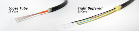
Tight buffered cables contain an individual buffer on each fiber stand, allowing for easy handling and quick termination. For common small fiber counts, this design delivers a smaller cable diameter than loose tube cables and is best suited for indoor environments. The most common designs for tight buffered cabling are distribution and breakout. For applications like moderate distance transmission for telecom local loop, LAN, SAN, and point-to-point links in cities, buildings, factories, office parks and on campuses. Tight-buffered cables offer the flexibility, direct connectability and design versatility necessary to satisfy the diverse requirements existing in high performance fiber optic applications.
Singlemode and multi-mode cables are another common types of fiber optic cables. Single-mode fiber strands are designed to interface with laser optic light sources for distances beyond 300 meters, while multi-mode strands or MM fiber patch cords are designed to interface with LED and vertical-cavity surface emitting laser (VCSEL) light sources for short-distance cabling runs.
Considerations When Installing Fiber Optic Cables
If you are considering using fiber optic cables in your installation, take a moment to review the installation guides. Firstly, for industrial installations, it is critical to consider and evaluate the environment. Additionally, as the fiber optic cables are more susceptible to damage during the stress of installation, therefore there are two specifications for bend radii—Bend Radii before installation and Bend Radii after installation. All hardware and support structures should follow the recommendations of TIA-569 and NECA/BICSI 568 Standards documents. Last but not the least, use cable management straps or cable ties to support cable bundles. Make sure these implements are fastened snugly, but not tightly around cable bundles.
Conclusion
There is without saying that the advent of fiber optic cable solutions has been one of the best things to happen to technology in recent years. With the demand on technology ever-increasing, fiber optic cables are becoming the preferred method of transmission over traditional coaxial solutions.
Posted by: angelina at
02:42 AM
| No Comments
| Add Comment
Post contains 642 words, total size 6 kb.
September 14, 2016
Cat 5e or cat 6 cables now are the mainstream of the copper network solution, but optical technology are progressing to promote higher category copper cables for the increasingly heavy-loaded data center solution. Cat 8 cables lately has been much talked about, especially after the TIA category 8 cabling standard approved. Category 8 is regarded as the next-generation twisted-pair cabling specification for higher data rate, but it is still under development. Here is what we need to know about the basics of Cat 8 cabling.
Main Features of Category 8 Standard
Cat 8 cable is especially designed to support 25G or 40G Ethernet data rate with a link distance of up to 30 meters, which is sufficient for most switch-to-server connections for top-of-rack (ToR), middle-of-row (MoR) or end-of-row (EoR) topologies. In addition, category 8 cabling is fully backward compatible with category 6A cabling, including RJ45 connectivity, and supports all Category 6A applications such as 10GBASE-T for a distance of 100 meters.
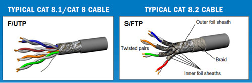
Category 8 cabling and components are specified with transmission performance of up to 2 GHz (four times the bandwidth of Category 6 cabling and two times the bandwidth of category 7) with more stringent alien crosstalk requirements. Meeting these requirements requires a shielded cabling system (F/UTP, S/FTP or F/FTP), just as seen in the above picture. What’s more, the cat 8 cables do not need more power to operate over shorter distances for 25GBASE-T/40GBASE-T application. The power needed to transmit a signal 30 meters at 40 Gb/s is approximately the same as the power needed for 10GBASE-T transmission for distances up to 100 meters.
How to Compare Category 8 to Those of Previous-Generation Twisted-pair Cabling Systems—Category 5, 6, 6A, 7, 7A?The cat 5e cables was introduced in 1999 with the use of 100-meter, 4-connector channel in structure cabling. The primary differences between category systems is the frequency at which the signal is transmitted over the cable. Cat 6 cables are designed to support 10Gbqs with a frequency of 500 MHz. While Category 7/7A as n advanced version of cat 6 cables offers a 100-meter 4-connector channel using shielded cabling, and has been designed to transmit signals at a frequency of 1000 MHz. Even though Category 7/7A operates at the higher frequency, there is no corresponding improvement in data rate over Category 6A because 10GBase-T is still the fastest twisted-pair-based data rate recognized by IEEE 802.3.
Category 8 is a significant departure from previous systems in that it uses a frequency of 2000 MHz, and is limited to a 30-meter 2-connector channel. Unlike Category 5e or Category 6A, which could use either unshielded twisted-pair (UTP) or shielded cable construction, Category 8 will require shielded cabling. The most likely cable construction for Category 8 will be 22-AWG S/FTP cabling. Category 8 is also unique in that the ISO standard will recognize two different classes of product. Class I is based on the traditional RJ45 connector, while Class II will accept non-RJ45 connectors similar to Category 7/7A. While both solutions will offer backward compatibility in terms of transmitting the lower category data rates (1G or 10G), the Class I solution offers a migration path using the RJ45 connector platform. For example, a customer might install a Category 8 jack-to-jack link now, but continue to use Category 6A patch cords until the active equipment is upgraded.
Given Category 8’s Capabilities, Where Is It Most Likely to be Deployed?
Category 8 cabling is designed to support emerging IEEE 25GBase-T and 40GBase-T needed as server-to-access-switch interconnect applications. This need has been identified and available, or under development, over optical fiber links for longer reach (up to 500 meters), or twinax links for short reach (up to 7 meters).
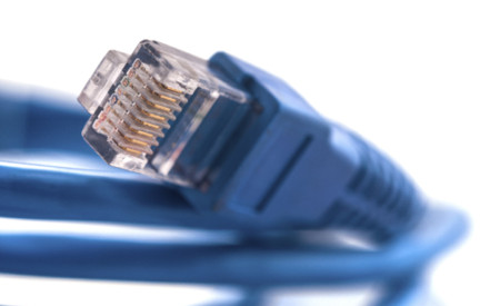
The opportunity for balanced twisted-pair as a cost-effective viable media option for the intermediate distance needs between 5 and 30 meters, sufficient to serve 20 cabinets or racks in a data center, led to the initiation and development of both the IEEE 802.3 application standards and the associated TIA as well as ISO/IEC Category 8 cabling standards.
How to Install Category 8 Cables?
Category 8 will be a shielded, field-terminable, and with a very high bandwidth. Thus there to be at least some improvements made to how jacks are terminated in the field to both meet this new bandwidth and to ensure a good bond with the shield. Additionally, contractors must make sure that the cable is properly grounded. If the connector companies do their job right, grounding the Category 8 cables and connectors will be a seamless process for the installer, which is all based on the RJ45 connector. Any component qualified as a Category 8 component will also meet requirements specified for Category 6A and lower components.
Conclusion
Cat 8 product recently is not available on the market now, but it is believed that in the near future cat 8 related items will be ubiquitous. Cat 8 cabling are meant to support 25GBASE-T and 40GBASE-T specifications, which will greatly propel the development of 25G and 40G network.
Posted by: angelina at
03:01 AM
| No Comments
| Add Comment
Post contains 839 words, total size 6 kb.
30 queries taking 0.1544 seconds, 115 records returned.
Powered by Minx 1.1.6c-pink.

