



August 31, 2016
Although cabling only represents less than 10 percent of the overall data center network investment, it outlives most network elements and treated as the most difficult and potentially costly component. With the datacenter cabling ranging from 1G to 10G, 10G to 40G and even to 100G, more complex cabling is required to ensure a good service or scalability for troubleshooting. In practice, there is no exact solution that will meet all of the cable management needs. However, two kinds of cabling systems can be applied—unstructured system and structured system. Just follow the guidelines and illustration highlighted in the article will go a long way to ensure you with the information required for the successful deployment of a cabling infrastructure in your data center.
Unstructured Cabling System
Unlike the structured cabling system with a managed patch panel, a unstructured cabling only occurs when optical links are deployed point to point or device to device without installing patch panels. In this situation, cabling pathways become congested with an entangled mess of two-fiber optical patch cords. Likewise, routing new patch cords in ceiling or floor trays all the way across a data center each time a new device is deployed is extremely inefficient.
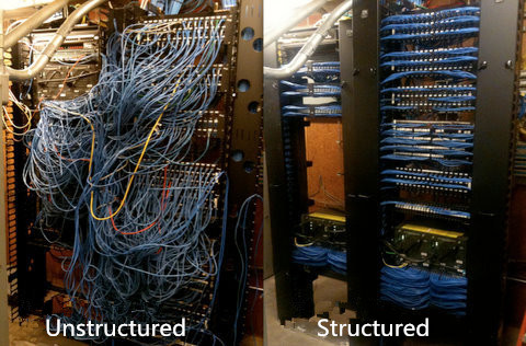
And this entanglement will bring difficulties in routing new patch cords in ceiling or floor trays all the way across the data center whenever a new device is deployed. That greatly influences work efficiency. What’s more, this system causes the overheating of data centers especially around the racks where cable clutter occurs.
Structured Cabling System
Structure cabling emerged as a way to better manage larger data center solution is a big step for the development of optical technology. Structured cabling system is a flexible, reliable and highly efficient for moving, adding and changing the infrastructure as the network grows. This kind of system requires additional investment on pre-terminated MPO cabling such as patch panel to create the cabling infrastructure.
Compared with the unstructured cabling, structured cabling architecture is generally easier to manage and more scalable. And, due to the use of trunked or shared horizontal cabling, it often carries a smaller cable footprint than direct-attach cabling. However, the flexibility of structured cabling presents potential downsides, including cost and link-loss budget. Nevertheless, existing large data centers will likely retain their structured cabling infrastructures, particularly for long-reach, zone-to-zone applications, where it generally remains the more practical choice. The following part will introduce 40G structured cabling solutions.
40G Structured Cabling Solutions
As noted before, structured cabling solutions allow for high consolidation of cabling into a compact patch panel, cabling and connectivity. The traditional duplex multimode SC or LC connections do not support 40G data rate standards, today the MPO technology is commonly found in cassette-based data center installation allowing for easy management and maintenance. Below are cabling solutions of 40G for cable management configurations with the use of MPO patch panel.
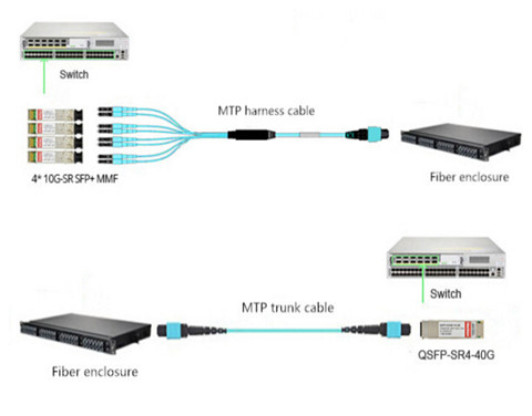
One method (seen in the above picture) uses MTP-LC harnesses to transition the MTP connector to LC leads through the use of fiber enclosure loaded with 4 fiber adapter panels (12xMTP Key-up/Key-down). This 12-fiber MTP to LC harness assembly breaks out 4 x LC uniboot legs connecting the SFP+ ports. The lengths of LC harness legs can be customized to adapt to different situations. But this often results in messy cable management. The other method uses MPO/MTP trunk cable and fiber enclosure loaded with 4 MTP high density cassettes (2 x MTP-12 to Duplex LC/UPC 10G OM4) to realize the interconnection. This 96-fiber 1RU rackmount fiber enclosure connects fiber patch cables LC to LC and MTP trunk cable. This method is specially used when the 4xLC ports are not located in close proximity on a single device or are being split between multiple devices. Because it’s more manageable to land the MTP trunk cables into fiber enclosure with individual LC ports for 4xLC patch cables.
Conclusion
Choose the most suitable cabling to support present and future network technology is essential for the long-standing performance of the data center. Structured cabling using an MTP cabling infrastructure is suitable for current 10 Gigabit Ethernet environments while maintaining protection for 40 Gbps environments and beyond. Compared with unstructured cabling, it might be a better solution for you. Except for the right knowledge of a structure cabling, the right tools, patience and discipline are also the key factors that will attribute to the masterpiece of your cable management in data center.
Posted by: angelina at
02:43 AM
| No Comments
| Add Comment
Post contains 744 words, total size 6 kb.
August 26, 2016
Generally for a home network, the most important consideration is the speed you have contracted for with your Internet service provider (ISP). And network adapters as an important element in wire management, are required to connect to the Internet with or without an Ethernet cable. There are many types of network adapters, an wireless one can help people connect to the home or office network as long as the computer is in the vicinity. This article will provide some information about network adapters that may be useful to potential buyers.
Main Features of Network Adapters
The wireless network adapter is quite similar to a memory stick in appearance. The device will usually insert into a USB port and has a LED light that indicates operability and power. The devices can be portable and quite effective. Some are slightly larger and may be the size of a credit card. Because of their size, the devices are convenient and easy to install. More designers are coming to appreciate the compactness of network adapters.
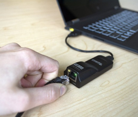
When the device is plugged in, it will scan for local networks to connect to and display them for the user. Users simply have to click the name of the network they wish to join. Any credentials that need to be provided should be provided, and this is all it requires to surf the network wirelessly. Most devices only require the credentials once, and it will boot each time it’s logged in.
The Important of Network Adapter
Network adapters are necessary for those who desire network connectivity. Network adapters bring so much more functionality and flexibility when it comes to connecting to the Internet. Wireless network adapters are even more desirable. Designers are recognizing that network adapters are instrumental to the success of the device. Local technology companies can provide network adapters at an affordable price to clients who need the functionality and the scalability. Network adapters are instrumental to connecting single or multiple devices to the Internet.
Software Drivers Are Necessary
Wireless network adapters need a piece of software called a device driver. These network drivers will allow applications to communicate with the network adapter hardware. When the network drivers are communicating with the hardware, the devices operate easier. Drivers can make current and past technology more compatible. If an upgrade is necessary from a PCI card or a PCMCIA, USB devices with update driver software is the preferable choice.
Backwards and Forwards Compatibility
Laptop computers will come equipped with a built-in WiFi card. When the wireless standards change and a new card is required, network adapters are usually backwards and forwards compatible. This is desirable if you want the newer and faster standard. For instance, most network adapters will support both the 802.11g standard and the 802.11n standard to ensure that they are both backwards and forwards compatible.
However to Ensure the Performance of Your Network Adapter
The network interface is where the data hits the computer. It’s the port or WiFi adapter that receives the data from the air or cable and translates it into something the computer can understand. No matter how fast the data arrives at the interface, it will only pass through as fast as the interface can process it. Many things can slow it down.
It’s important to remember that an interface that is capable of higher speeds than your network provides will not help things go faster. Spending money on a Gigabit network card won’t give you 1000 Mbps if your ISP is only supplying 25 Mbps.
Furthermore, a Ethernet cable in a cable management systems used to achieve the connectivity will also pose threat to the internet speed. Ethernet cables are presented in different categories. The most commonly used is Cat5, Cat5e and Cat6. CAT 5, rated at 100 Mbps; CAT 5e rated at 1000 Mbps; and CAT 6 rated at 10,000 Mpbs. CAT 5 is fine for most internet access through DSL or cable, while CAT 5e works well on connections over 100Mbps, as well as Gigabit business networks and home fiber optic connections. CAT 6 is probably overkill for most home networks, but is useful for business networks over 1 Gbps.
Other than cables used in home network, there are other factors that can throttle the performance of your network. Therefore, to use an external test server tests not only your home setup, including your adapter, but everything between you and the server doing the test.
Conclusion
To select the right adapter for your situation, you’ll want to have an adapter that exceeds the maximum speed of your network, while taking into consideration any likely future improvement.
Posted by: angelina at
02:36 AM
| No Comments
| Add Comment
Post contains 774 words, total size 6 kb.
August 24, 2016
As audio video systems and installations have become more complex over time, it is common for people to use HD TVs, HD media players, and other home theater systems. Additionally there seemed to be a big variance in quality between brands, especially when it came to extending HDMI signals. Therefore, the introduction of HDMI technology is a game changer and highly appreciated by overall users in this days. Just as fiber jumper connecting optical equipment, HDMI cables offer long-distance HD audio and video signals transmission playing an important role in achieving brilliant performance. Today’s article will have a brief introduction to this cable.
HDMI Cable
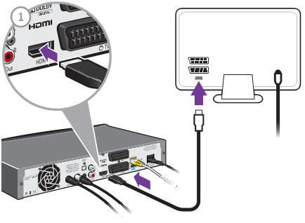
HDMI ((High-Definition Multimedia Interface) cable is composed of four shielded twisted pairs with several separate conductors for transferring data over video/audio devices. A HDMI cables are defined into two cable categories: one is the Category 1-certified cables, known as standard HDMI cables, the other is Category 2-certified cables, also called high speed HDMI cables. HDMI cables has not been specified the transmission length. A cable of about 5 meters (16 feet) can be manufactured to Category 1 specifications easily and inexpensively by using 28 AWG conductors. With better quality construction and materials, including 24 AWG conductors, an HDMI cable can reach lengths of up to 15 meters (49 feet). HDMI cables are expensive than the regular Cat6/Cat7 cables. Just as anything else, whether you want to use the expensive but high-performance HDMI cables or cheap but low-performance Category copper cables like Cat5e/Cat6, it depends on what inputs you tech has. The below part lists the current usage of HDMI cables, and you can look at the solutions that interest you. The following image shows the image of a HDMI cables connecting box and HDMI socket of TV.
Difference Between an HDMI Cable and a DVI Cable
HDMI cable and DVI cable as two two input-output media interfaces in home network are posing difficulty in distinguishing them. In fact, the biggest difference between these two transmission media lies in their layout. An HDMI cable is more compact and resembles a USB cable, while a DVI cable is usually bigger in size. Another major difference is in capability: the HDMI supports audio and video, whereas the DVI is strictly video-only.
Applications of HDMI Cables
- Boosted HDMI: HDMI cables, with a booster integrated into their structure use the 5v power rail of the HDMI signal to carry the data further without loss of fidelity. This cable, compared with the normal HDMI cable, is intended to make longer cable runs, but it can also be used to make a short cable thinner and much more flexible. HDMI cables with integrated booster chipsets are more expensive than their basic counterparts, and so far only cater to 1080p content due to the loss of bandwidth over the extended length, but they can reach 40 meters.
- HDMI over CAT: It is not a new concept to use Cat5 or Cat6 cables to extend an AV source. HDMI recently make use of this technology for stable extended runs—sometimes even using existing network cabling. Due to bandwidth limitations, most CAT extenders only support 1080p, but some can handle 3D, too. Configuration is more complex than regular cables, and interference can be a big problem in some environments, but with a good HDMI over Cat5/6 Extender, you can run 50 meters.
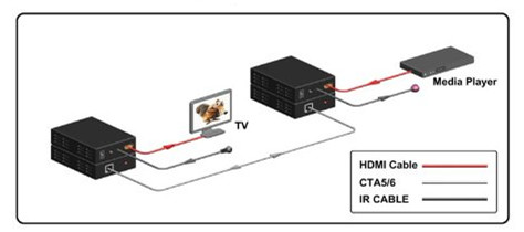
- HDMI over Fiber Optics: Fiber optics for HDMI, compared with HDMI over CAT, carries the highest price premium, but they have the much better capacity to outstrip copper based cables for distance by a large margin. The added benefit to this cable type is flexibility with a maximum distance of 45 meters. The optical core is much smaller than Boosted HDMI, but can go the same distances. Note that some companies have kits which run much longer, but it of course will cost far more!
- HDMI over Wireless: Wireless technologies vary between models, but one thing they have in common is they don't generally go as far as cables do. Line of sight is 10 to 15 meters, and through walls can be as low as 5 to 8 meters. Unless you can't run a cable at all, a lead will beat Wireless every time. Wireless is also limited by bandwidth to 1080p, and only the best units can handle 3D.
Some Terms Appeared in the Above Part
1080p refers to an HDTV format which has 1080 horizontal lines of resolution. The p stands for progressive scan. The traditional analog video uses an interlaced scan, which draws the odd lines, then even lines of each frame in sequence.
AWG is short for American Wire Gauge, which is a common unit of wire measurement. AWG expressed in a HDMI cable refers to the size of the conductors within the cable. With wire gauges, smaller numbers actually refer to larger wires. This means a 24 AWG cable has a thicker conductor than a 28 AWG cable. The benefit of a thicker conductor is the ability to effectively transmit an HD signal.
Plenum refers to the air-handling spaces in building construction above the ceiling and beneath the floors. Some building codes require Plenum-rated cable, which has a low-smoke jacket that burns slower in the event of a fire and emits less toxic smoke.
Summary
This article isn’t a definitive guide to HDMI cables, but for the sake of simplicity we just provide some basic information about industrial and commercial applications of HDMI cables. If you are on the fence to install a fiber optic network, always use the shortest length of cable you can live with, and ensure they're certified by the industry bodies. What’s more, it is advisable for you to save your money for other home network components and get your HDMI cables as cheaply as possible.
Posted by: angelina at
03:24 AM
| No Comments
| Add Comment
Post contains 968 words, total size 7 kb.
August 17, 2016
When planning for a long-term cabling solution for your data center, it is important to consider future transmission speeds and the infrastructure to support them. Data center houses equipment like servers, storage units, backup power supplies and other equipment, which act as the heart of a building or campus. And all these equipment require high-bandwidth cables to connect them. The cabling in data center mainly comes in two forms—fiber or copper. To link the devices in data center, unshielded twisted pair (Cat5e/Cat6) and fiber optic fibers (MM fiber patch cords and single-mode fiber) are commonly used. This article will focus on cabling solution for data center, and provide the cost-effective solution to you.
Twisted Copper Solutions For The Data Center
2006 witnessed the publication of the the IEEE 802.3an standard, meaning that users can use the twisted copper cabling or 10GBASE-T to support 10 Gigabit Ethernet. Compared with the former IEEE 802.3ak or 10GBASE-CX4 standard, 10GBASE-T standard has the advantage of supporting 10 Gigabit Ethernet up to 100 meters. What’s more, the 10GBASE-T using structured wiring systems based on the RJ45 connector is less costly than the 10G optical transceivers for supporting the same Gigabit Ethernet. All this attributes to the development of the copper twisted-pair cabling for horizontal, or non-backbone, distribution between LAN switches and servers.
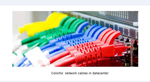
UTP (unshielded twisted pair) cabling is a widely adopted copper cabling solution due to its support for both voice and data applications. A UTP cable consists of insulated, copper wires twisted around each other to reduce crosstalk and electromagnetic induction between pairs. Typically a twisted pair will be enclosed in a shield (STP) that works as a ground; in other cases (UTP), the pair remains unshielded. UTP cables are often referred to as a Category cable, such as Cat5e, Cat6, or Cat7, etc.
Cat5e cables had been the standard solution and often used for legacy equipment or lower bandwidth needs. But Cat6 is the most common copper type in new installations today, especially for 10G Ethernet application. Cat5e will soon be going away, with available options being Cat6, Cat6a and Cat7. These options offer increased levels of performance and improved installations. All of these cable types can adequately provide you a connection. The differences between them lie in their transmission speed capabilities and costs.
Fiber Optic Solutions For The Data Center
In a data center, bandwidth distributed to servers and other devices may range from 1 Gbqs to 10 Gbqs or more depending on application and data center models. Fiber optic cabling are usually worshiped by overall users owing to numerous advantages. For instance, compared with copper cabling, fiber systems can provide up to 60 percent space savings over copper cabling, and it also have a greater bandwidth and error-free transmission over longer distances allowing network designers to take advantage of new data center architectures.
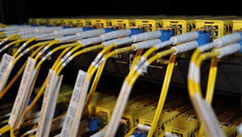
In practical terms, fiber cables are comprised of light, which reduces signal interruption, allowing for signals to be carried longer distances seamlessly. Though fiber cables are highly sought after, the cost to purchase and install has decreased throughout the years, making them a reasonable choice for companies seeking a reliable, scalable solution. The fiber optic cables can be mainly divided into two parts, that’s multimode and single-mode fibers.
The multimode fiber type can be separated into categories: OM1, OM2, OM3, OM4. Applied for short distances, multimode fibers have a high light-gathering capacity, meaning the use of lower cost, lower wavelength technologies like LED and vertical-cavity surface-emitting lasers (VCSELs) can be employed. For longer distances, single-mode OS1 and OS2 are used; single-mode fiber uses lasers to achieve higher speeds and further distances. Additionally, fiber optic cable terminated with different optical connectors (like SC fiber cable) are also widely utilized in data centers. Fiber optic cables are critical to network performance as they do more than join servers and connect switches. They are the foundation of your technology environment. Thus it is important to have the best options for your optical network.
Field-terminated vs. Pre-terminated Fiber Solutions
In commercial building installations, an optical fiber cabling link is typically assembled in the field at the job site. The cable is pulled in from a reel of bulk cable, cut to length, attached to the patch panel housing and terminated with field installable connectors on each end. The terminated ends are then loaded into adapters in rack or wall mountable housings. Finally, the complete link is tested for continuity and attenuation.
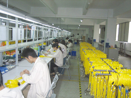
The most efficient optical infrastructure is one in which all components are pr-eterminated in the factory see in the above picture. Connectors are installed, tested and packaged in the factory. The installer unpacks the components, pulls the preconnectorized cable assembly into place, snaps in the connectors and installs the patch cords connecting to the end equipment. This is the fastest installation method and provides the best solution for turning up servers quickly and lessening the risk of not meeting the customer’s availability expectations. The design and product selection process remains the same with selection and specification of fiber type, fiber count, cable type, connector type and hardware type appropriate for the environment.
Conclusion
There is no absolute solution to utilizing fiber or copper cabling for data centers. Twisted pair cabling wins the broad acceptance among users owing to the horizontal medium, low initial cost, and the ability to deliver higher data rate LAN services and the flexibility to use one medium for all services. Therefore, in the majority of situations, copper cabling remains the preferred choice for the final link to the desktop, and other short links such as those found in data centers. However, with the speeds increasing and more copper cables installed, copper-based LANs will require more complex and expensive electronics. It might be inappropriate or impractical to implement in many current building environments.
While fiber optic cabling’s significant bandwidth distance gives it advantages over twisted pair in centralized architectures. Thanks to its high performance and high density, fiber optic cabling becomes an important factor where equipment density and heat dissipation are a concern. To sum up, whether to use copper or fiber for network cable type, the data center must have the best and fastest cabling.
Posted by: angelina at
03:55 AM
| No Comments
| Add Comment
Post contains 1039 words, total size 8 kb.
August 16, 2016
If you are still using a 100BASE network, or GBIC transceiver for a small office, you may run into the limitations of last decade's technology. Because the 100BASE standard network is just fine for a small office, but it isn't sufficient to handle heavier network use. As your network expands, you might experience problems like: dropouts in your VoIP calls, Sluggish data retrieval speeds, or poor video streaming quality. If you have encountered any of this, maybe it’s time to start thinking about an upgrade to gigabit Ethernet, which moves at ten times the speed of traditional Ethernet. This article will explain the Gigabit Ethernet in the following aspects: the compatible SFP transceiver, the difference between twisted copper and fiber optic Ethernet.
Compatible SFP Transceiver
When contemplating an upgrade to gigabit Ethernet, there are a number of issues involved in the network transition. But one of the most immediate concerns people have is how much new hardware they'll have to purchase. The good news is that one of the basic issues providing connectivity is generally quite easy.
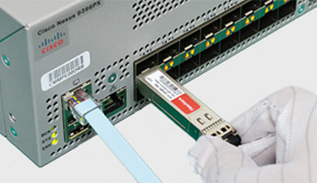
The representative of the optical transceivers for Gigabit Ethernet is Small Form-factor Pluggable (SFP). These Small Form-factor Pluggable slots allow transceivers like the GLC-SX-MM to be plugged in and provide instant gigabit Ethernet connectivity. In the last few years, when you purchased your networking equipment, it should have some industry-standard SFP ports, based on a Cisco standard. And you can only purchase the original expensive SFPs. However, the monopolized SFP market is unhealthy for the development of optical technology, nowadays people can appreciate the low price and high performance of compatible SFP transceivers from OEM vendors.
How to Ensure the Compatibility of the SFP Transceiver
Although the OEM or alternative party compatible SFP transceivers are much cheaper than the original ones, people are hesitated to use them. In fact, there are mainly two factors that will have an impact on the compatibility of the SFP transceivers. First, does the SFP optics require DDM function? Second, does the host equipment check the ID code and lock out alternative party components?
Certainly from our experience, most Cisco core equipment and routers do lock out all but Cisco ID SFP modules. We do not have an extensive report on what Cisco equipment does and does not lock out third party SFP.
The only way to know for sure is to try an authorized component if the host equipment rejects it. Remember, the compatibility has nothing to do with the functions of the transceiver, only in recognizing ID code and selecting to lock out third party SFP or not.
Fiber Optic Cabling Over Copper-wire Cabling
Choose to use copper-wire cabling or upgrade to fiber optic cabling in your offices is another consideration when installing a network. There is no doubt that fiber optics provide several advantages over copper, but it is more expensive than copper cabling. In addition, fiber optic supports far longer cable lengths than twisted copper.
Copper can only run for around 100 meters, whereas fiber can go between 200 and 500 feet, or more, without signal loss. Fiber has gives off no radio interference, allowing it to coexist more easily in an office with a lot of wireless devices. Because of the lack of interference, fiber is also harder to hack into than copper.
For equivalent data rates, optical cable is thinner and lighter than copper wire, and it does not need to be shielded. For these reasons, an optical cable is often lighter in weight and less bulky, and has a smaller bend radius, than the equivalent copper cable, especially with longer cables. These advantages of fiber provide more data center configuration flexibility.
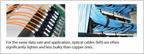
Just as with copper, a standard GLC-SX-MM transceiver links fiber optic Ethernet with your existing equipment. Or the GLC-SX-MM-RGD transceiver is also just great for your network, which is the 1000BASE-SX SFP GLC-SX-MM transceiver with DOM support.
For future proofing, moving away from copper is probably a good idea. Fiber optics are growing steadily in popularity among businesses which have taken over large office buildings, created expansive complexes, or need to collaborate with remote offices in real time.
Additional Information
The biggest advantage of Cisco's SFP system is that it's entirely hot-swappable. It doesn't matter what the device is, from servers to your switch to simple Ethernet cards: If it has an SFP port on it, it can support a multitude of transceivers for different functions, through one standardized interface. In fact, that standardization means that third parties can produce transceivers which are as good as official Cisco units. So, if you decide that fiber optic gigabit Ethernet is what you need for your future business communications needs, the GLC-SX-MM transceiver is truly simple to install and use.
Conclusion
End-users are wondering about whether they should upgrade to higher-bandwidth network as the existing network like 100BASE standard is fine for their network. However, the transition to higher internet speed is going to happen sooner or later. There are several different gigabit Ethernet standards out there, so keep in mind to see which best fits your vision for the future of your business. Note that you'll need transceivers like the GLC-SX-MM to connect your existing devices to the new network.
Posted by: angelina at
03:24 AM
| No Comments
| Add Comment
Post contains 878 words, total size 7 kb.
August 11, 2016
Cisco system introduced the Nexus series switch in 2008 that are modular and fixed port network switched designed for the data center. The Cisco Nexus series switches ranges from Nexus 1000v, to the newly released Nexus 9516, which are warmly welcomed by users. This article will introduce the Cisco 6004 switch and highlight its 10G and 40G cabling options.
Cisco Nexus 6004 Switch
Cisco Nexus 6004 switch is a model of Nexus 6000 series. Previously,, the Nexus 6000 series was meant to be focused on the Cisco 40G aggregation products, and the 5500 and 5600 series on 10G. However, Cisco decided to merge the product portfolios. Thus Nexus 6000 series switch delivers high-density 10 and 40 Gigabit Ethernet connectivity in an energy-efficient, compact form factor, so does the Nexus 6004 switch.
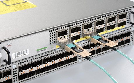
The Cisco Nexus 6004 switch is a high-density, low-latency, high-performance device for 10G & 40G Ethernet and Fibre Channel over Ethernet (FCoE) infrastructure, with a compact four-rack-unit (4RU) switch providing line-rate Layer 2 and 3 switching. This switch offers 48 x 40-Gbps ports on the base of the chassis and 4 line-card expansion module (LEM) slots; 12 x 40-Gbps port LEMs can be plugged into each slot, for a system total of 96 x 40-Gbps ports in an Enhanced Quad Small Form-Factor Pluggable (QSFP+) form factor.
Features and Capabilities of Cisco Nexus 6004 Switch
- High-performance—The Cisco Nexus 6004 can support up to 384 SFP+ connectivity over breakout cables or 96 40 Gbqs line rate. It also offers unified ports for LAN and SAN convergence.
- Future Proof—The Cisco Nexus 6004 support for all the card expansion modules across the 6004 Chassis. The Cisco Nexus 6004 is also equipped with eight expansion slots for accommodate network growth.
- Operational Efficiency—This switch is equipped with advanced analytics toolkit, VXLAN support for virtualized and cloud deployments (supported on Cisco Nexus 6004X), and dynamic Fabric Automation (DFA) and PowerOn Auto Provisioning (PoAP) for automated virtualized and cloud deployments.
Cabling Options for Cisco Nexus 6004 Switch
As noted before, the Cisco Nexus 6004 switch offers 10G and 40G connectivity. Numerous 10 and 40 Gigabit Ethernet connectivity options using Cisco 40GBASE QSFP and QSFP+ breakout cable can be used in this switch. The following image presents two physical connections for Nexus 6004 switch.
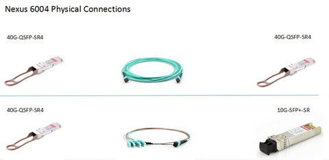
In a 10G deployment, a permanent structured cabling link would be deployed using these MTP-based trunks to create connector patching fields at each end. Then short MTP or LC jumper patch cables would be used to make the connection from the patch field to the QSFP+ or SFP+ optics at the switch port. The MTP patch-panel field allows the end device to be connected to any port across multiple Cisco Nexus 6004 devices because the devices terminate at the patch-panel field. The following figure shows a Cisco Nexus 6004 that is connected to the base ports of a Cisco Nexus 5500 platform switch.
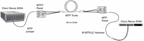
These endpoint connections will be MTP and LC, respectively, and the structured cabling infrastructure maintains MTP trunks and panels. This approach will require a MTP-to-LC harness assembly to make the connection from the termination patch field to the Cisco Nexus 5500 platform. A MPO jumper can be used to make the connection from the termination patch field to the Cisco Nexus 6004.
For 40G connectivity, Cisco Nexus 6004 switches can support 40G direct attach cable (DAC) integrating QSFP connectors for short-reach 40G application, or supporting 40G active optical cable (AOC) for longer-reach application. FS.COM provides a full range of 40G QSFP+ DAC cables including passive (lengths up to 7m) and active cables (lengths up to 10m). In addition to the QSFP+ to QSFP+ DACs, it also offers the QSFP+ to 4 x SFP+ breakout DACs which are ideal for Cisco device user to run 40G over existing traditional 10G backbones.
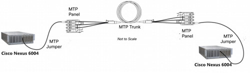
The image below shows the 40G cabling connectivity between two Cisco Nexus 6004 switches. The MTP trunk cables used in this configuration create permanent fiber link between patch panels, and allow full support of 40Gbqs flows between the devices.
Conclusion
The Cisco Nexus 6004 switch provides can be deployed in multiple scenarios—direct-attach 10G and 40G Ethernet access and high-density fabric extender aggregation deployments. For those who want to upgrade to 10G Ethernet, the switch scales up to 384 ports of 10G Ethernet interfaces. And you can easily meet increasing demand for 40G Ethernet connectivity up to 96 QSFP+ interface ports. What’s more, the Cisco Nexus 6000 series can adapt to increasing bandwidth demands with low power and a compact space profile, providing savings in capital expenditures and operating expenses.
Posted by: angelina at
03:12 AM
| No Comments
| Add Comment
Post contains 765 words, total size 7 kb.
August 10, 2016
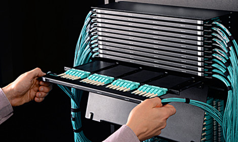
The data center is the heart of a fiber optic network. To ensure its long-term reliable network performance, all the optical equipment within data center should be well organized. However, the current multi-fiber counts and high-density optical cabling put strain in the cable management. Fiber patch enclosure provides solid fiber-optic-link protection and space-saving cable management, which is becoming a must-have component in data center. There are several fiber optic enclosures available on the market that are widely utilized in data center or server room. This article will briefly introduce the commonly used fiber enclosure designs to better meet your data center requirement. LC to LC fiber cable and patch panels are mounted in a fiber enclosure in the following picture.
Fiber Enclosure Designs
Rack mount fiber enclosure is the commonly used type in data center as it provide a convenient and rugged termination point for fiber jumper cables. This rack mount enclosures offer a flexible connectivity system using a variety of adapter plates and MPO cassettes. The enclosures work equally as well with armored cable as they do with multiple trunk cables and are available in 1U-4U versions.
1U enclosures fit standard 19-inch racks and have rear cable management rings. 2U, 3U and 4U enclosures are designed for side or rear trunk cable entry, have removable front and rear covers, edge guards on the front for cable assembly protection and front and rear cable management rings. 2U, 3U and 4U enclosures also fit standard 19 and 23-inch racks and have a clear plastic, removable front door that can be outfitted with a label for easy identification of connections.
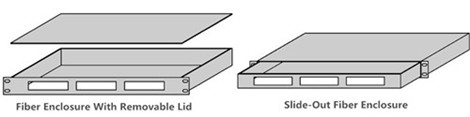
Except for different size, there are two types of rack mount enclosures: fiber enclosure with a removable lid and slide-out fiber enclosure (see in the following figure). The slide-out version is typically more expensive than the other version. But slide-out fiber enclosure can allow customers to remove the whole enclosure from the rack, thus, it can provide easier internal fiber connection access.
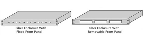
As for the design of the fiber enclosure front panel, two commonly used types are fixed front panels and removable front panel. The fixed front panel can be loaded with appropriate fiber optic adapters, while the removable front pane can accommodate several fiber optic adapter panels or cassettes just as seen in the following image.
How to Select the Fiber Enclosure
If this is your first time to install a fiber optic network, you should follow the instructions below. Only in this way can you satisfy your installation requirement, and matched your budget as well.
- Physical requirement
First, list all the requirement that will be mounted in the enclosure and their complete measurements:height, depth, width, weight. All of these figures will ultimately determine what type of fiber enclosure you will need. Note that always select a bigger fiber enclosure for all your existing equipment as well as for future proof.
- Critical accessories
A fiber enclosure should provide plenty of grommeted access points through the rear and top of the cabinet, as well as through the bottom for raised floor installations. Not only are the fiber optic cables mounted in the fiber enclosure, but devices like hubs, routers, patch panels, and monitors are needed to be mounted in the enclosure-network.
All servers should be protected by an uninterruptible power supply(UPS) system, available in a variety of rack-mount configurations. Thus power protection is needed. Remember that any accessories that are not rack-mountable will require additional trays, shelves and mounting accessories.
- Budget
Money is always a main considerations. Thus choose the fiber enclosure that can meet your premium features at a very competitive price is the number one task. People are usually in a dilemma about whether to choose a equipment that are suitable for now or the expensive one for future proof. It is hard to say, but a premium enclosure is a durable item that will provide services for years to come.
Summary
High density fiber enclosures can maximize the amount of active equipment in a data center by minimizing the footprint of the networking infrastructure, but there’s a problem—all that fiber in a small amount of space creates problems when changes need to be made. Therefore for easiest access, quick-release side panels should be a top priority when selecting an enclosure.
Posted by: angelina at
04:01 AM
| No Comments
| Add Comment
Post contains 720 words, total size 6 kb.
August 03, 2016
In the fiber optic network, a carefully constructed network requires calculated planning and a high level of installation. It is not as easy a cavemen can do it, as many factors should be taken into account when installing a fiber optic network, such as construction costs, time constraints, existing infrastructure, and so on. There are two main types of land based network fiber optic installation—aerial and underground. This article will talk about these two cable installations in detail.
Aerial Fiber Construction
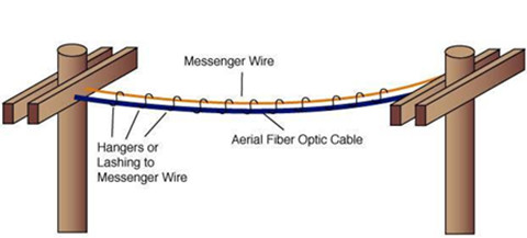
The fiber optic installation that occurs when fiber jumper is installed along a line of utility poles, is known as aerial fiber construction. When installing a placing aerial cable, besides the cables, a support strand is needed as well. A support strands can be deployed along the route first, with fiber pulled and lashed to the support strand later. Or the aerial fibers can be pre-lashed, making the installation less complex. Lashing refers to the process of securing the fiber cable to the support strand via lashing wire. When placing cable on a pole, the required spacing distance varies depending on the type of cable or equipment. These requirements are often set by local, state and national standards.
Underground Fiber Construction
Underground fiber construction refers to the fiber installation that occurs when fiber optic cable is installed under the ground in pipes, or conduits. The depth of the underground cables varies by many factors; however, it is typically between 12-36 inches below surface level. In underground fiber construction, the fiber optic cables are buried in a trench, but In colder areas, fiber cables are buried below the frost line to protect the cables from being damaged.
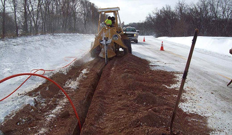
There are three main subcategories of underground fiber installation including direct buried, air-blown or micro trenching. In a direct buried cable construction, the fiber optic cable is installed directly into the ground rather than in protective conduits. When fiber optic cable is installed through a conduit via air, the process is known as air-blown or cable-jetting construction. And in air-blown installation, a device injects a high volume of air into the duct at high pressures to blow the cable through. Micro trenching construction occurs when the fiber optic cable is installed underground by way of a small groove, instead of a larger trench. Each of the above underground installations have a variety of benefits and are used in varying, and case specific scenarios.
Pros and Cons of Aerial and Underground Deployment
Aerial cables are one of the most preferred and cost-effective solutions for the end user, because installers can reuse existing pole infrastructure without digging up another roads to bury cables or ducts, what’s more, aerial cable construction is easily modified to add additional capacity.
However, aerial deployment is more susceptible to damage. The falling tree branches, high winds or ice storms, vehicle accidents, animals that chew on the fiber all can make the aerial cable strain or break. Therefore, calculations on the strength of both the cable and poles need to be taken into account when determining span lengths.
But it will typically takes some time and money to make ready requirements if poles and cable need to be made stronger. It is a good solution to the areas with existing pole networks or rural environments without urban restrictions.
While many customers do prefer their services, including fiber cables, to be installed underground. Unlike the aerial deployment, buried fiber deployments are less susceptible to wind and ice damage as they are buried below the layer, which makes it often at least ten times more reliable than aerial routes, especially where poor weather is common.
However this might be a costly solution because the cable needs to be buried deep in the ground to protect it from accidental damage. The deeper an operator has to dig, the more costly it is. Never to mention that if a buried direct cable is broken, it is expensive to repair. These buried direct cables cannot be removed and replaced because it tends to be firmly anchored into the ground.
Conclusion
As this blog shows, choose which method to install a fiber optic network will depend on a variety of factors including the landscape, cost of the labor and equipment, and so on. Both of the two deployment methods presents advantages and disadvantages that must be carefully evaluated by case basis.
Posted by: angelina at
03:51 AM
| No Comments
| Add Comment
Post contains 732 words, total size 6 kb.
32 queries taking 0.2972 seconds, 91 records returned.
Powered by Minx 1.1.6c-pink.

