



April 29, 2016
The rapid growth in storage and computing services is driving an expansion in both the physical size and overall computing power of the modern data center. This high-speed data interconnects linking the individual optical elements within a data center are typically comprised of fiber optical solutions (multimode or single-mode). Limited to short linking distances, multimode fiber interconnects are most often used to provide server-to-server or server-to-network switch connections within the same rack or chassis. Inter-rack and inter-chassis connections, which usually require greater reach and higher bandwidth, demand a single-mode fiber optic solution and are enabled by WDM-based parallel optical transceivers. Data rates of 10 Gbqs and higher are now commonplace in the modern data center, here is what you should know about data center cabling solution.
Multimode vs. Single-mode Fiber Solution
Data rates and link distance are the two important parameters typically characterized for fiber optic interconnect. When considering both of these requirements for a given application, link distance plays a key role in determining what type of optical module or fiber infrastructure to deploy. Applications with individual channel rates of 10 Gbqs requiring link distances of less than 300 m have traditionally been serviced by Vertical Cavity Surface Emitting Laser (VCSEL) based solutions operating over multimode fiber. These applications are often referred to as "Short Reach†by industry standards. For example, the 40GBASE-SR4 of the IEEE 802.3ba physical layer standard defines a 4-lane parallel optical interconnect for operation up to 100 meters in length over OM3 multimode fiber. Take Cisco QSFP-40G-SR4 as an example, this Cisco 40GBASE-SR4 transceiver (see in Figure 1) can support a link distance of up to 150m. Under this standard, 40Gbqs switch-to-switch uplinks can be realized using QSFP+ optical transceivers and MTP connector-based parallel multimode fiber cables. Besides 40GBASE-SR optics, 40G QSFP+ cables (AOC or DAC) are also a practical 40G solution. QSFP+ to 4SFP+ Passive Copper Cable (e.g.HP JG330A) provides a cost-effective solution for 40G short-reach interconnect application.
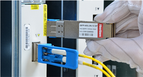
So called "Long Reach†applications typically involve link distances on the order of kilometers, and rely on more costly Fabry-Perot (FP) or Distributed Feedback (DFB) laser-based solutions running over single-mode fiber. While single-mode solutions provide a greater maximum link distance, they typically do so with higher power dissipation, and as mentioned previously, a higher module cost. Historically, multimode solutions could comfortably satisfy the switch-to-switch interconnect demand within the data center since link distances greater than 300 m were rarely, if ever, required. Now, with the rise of the Mega Data Center comes the realization that maximum switch-to-switch spacing may actually exceed 300 meters, and that a longer reach multimode solution is needed.
Short Reach With Multimode Fiber
Multimode fiber (MMF) has become widely used for up to 10Gbqs. It provides the lowest cost and lowest power connectivity with trouble-free installation for the data center designers. But MMF is running out of bandwidth at 10G, so parallel optics at 40G uses 4x10G channels and uses 10x10G channels for 100G, which has a great impact on the fiber count needed to support equipment. MM links at 10G are also power limited due to the bandwidth penalty caused by the limited modal bandwidth of the multimode fiber. MM links may only have ~<2dB loss budgets meaning that the data center cable cannot have many interconnections especially with the MPO multifiber array connectors which are inherently higher loss than single fiber ceramic-ferrule connectors like LCs and SCs.
Thus parallel optics assemblies use the MPO connector which has 12 or 24 fibers per connector. The limitation of parallel optics with MPO connections includes the masses of fibers required and the fewer interconnects allowable because of the typically higher loss of the MPO connector. Here is an example of a 40G and 100G solutions on multimode fiber. 40G uses a 12 fiber MPO with 4 channels each at 10G for transmit and receive on separate fibers, so there are 4 transmit and 4 receive fibers. Since the MPO connector has 12 fibers, the center 4 are unused just as shown in Figure 2.
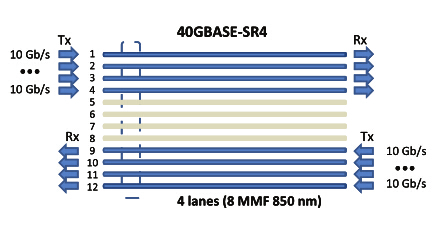
100G uses 10 channels each at 10G for transmit and receive on separate fibers on a 24 pin connector, so there are 10 transmit and 10 receive fibers. Since the MPO connector has 12 fibers in each row, the center 4 are unused. There is another version of 100G being developed that uses 4 X 25g channels which will have shorter reach. This design should use a connection scheme like 40G on a 12 fiber connector.
To sum up, multimode transceivers use inexpensive 850nm VCSELs so the transceivers are cheaper than singlemode but the fiber optic cable plant uses many multimode fibers so the cable plant is more expensive.
Longer Reach with Single-mode Fiber
Single-mode fiber are more preferable for unlimited bandwidth and distance capability when used in data centers. Unlike the parallel 10G channels used with MM fiber, single-mode uses wavelength division multiplexing (WDM) to transmit multiple channels over one fiber at different wavelengths. Thus 40G uses 4X10G wavelengths and 100G is achieved using 4x25G wavelengths. CWDM transceivers cost more than parallel MM transceivers at the current time, but the cabling cost is much lower and expected higher quantity usage will drive costs down. Look what 100million users did for the lasers and CWDM used in fiber to the home (FTTH.)
Conclusion
The rapid expansion of telecommunications networks, and data services, measured either by data volume or bandwidth, means fiber optic technology will be a significant part of future systems. Compared to multimode cabling solutions, single-mode technology is more flexible, lower power and higher bandwidth but more costly.
Posted by: angelina at
07:55 AM
| No Comments
| Add Comment
Post contains 936 words, total size 7 kb.
April 27, 2016
In optical communication networks, there are many devices fundamental to performing smooth technical operation. One indispensable system is called optical transceiver module. A transceiver combines a transmitter and receiver to form a unit and uses the same channels. Optical transceivers are typically found in various form factors, including SFP, GBIC, SFP, XFP and X2 etc, which are often used for computer networking purposes.
Whenever you need to deploy an optical network, you immediately come to think of Ethernet standards and relevant devices. Well, the fact is, some types of Ethernet networks require the utilization of specific types of transceivers. What’s more, you need to balance the budget and your network requirement. For instance, if you are looking for 10G XFP transceivers, you must know about something to get transceivers at very reasonable rates prior to making your decision. The following article will provide some suggestions to help you select the most suitable optical devices for your infrastructure.
XFP Transceiver—Definition & Classification
With the progress and advancement in technology, more and more equipment with latest techniques are being introduced every day. The XFP transceiver is a hot pluggable component intended for 10G system applications. XFP transceiver is also a protocol autonomous optical translation device utilized in various applications such as 10Gbps SDH/SONET, DWDM fiber optic networks and related applications. The XFP transceivers satisfy the relation to MSA launched by various popular companies on the market today. There are numerous XFP transceivers available on the market, including 10GBASE-ZR XFP, 10GBASE-ER XFP, 10GBASE-LR XFP, and 10GBASE-SR XFP. The most widely used is 10GBASE-SR XFP which has a working distance of 300 meters maximum via OM3 MMF.
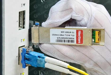
The other types of XFP function with SMF:
- The maximum distance of 10GBASE-LR XFP is 10 kilometers via 1310nm SMF;
- The maximum distance of 10GBASE-ER XFP is 40 kilometers via 1550nm SMF;
- The utmost distance of 10GBASE-ZR XFP is 80 kilometers via SMF.
10GBASE-LR XFP is widely utilized in telecom field, take XFP-10GLR-OC192SR as an example. This Cisco compatible 10GBASE-LR XFP can support a distance of 10km over single-mode fiber. Juniper XFP-10G-L-OC192-SR1 possesses the same function with the XFP-10GLR-OC192SR, but they are offered by different vendors.
Select the Most Suitable Optical Transceivers
After the certification of X2 transceivers and XENPAK, this XFP transceiver is the new invention for 10G solution. Various vendors are available in providing 10G XFP transceivers. You can purchase these transceivers from a local store or over the website. Since many companies have their personal website where people can purchase at home, but the most challenging part is to find a reliable vendor that provides top quality products at affordable price. To simplify your process, two most widely used and reliable brands of transceivers are Cisco and Juniper, just as I have listed above. Just make sure you perform some reading on the web for reviews and advice from people who have used these brands, which will help you create a more informed purchase decision and cut down your cost.
However, the Cisco or Juniper XFPs are too expensive. People can not afford the high cost. Thus many designers are turning to compatible ones which have the same functions and ideal compatibility with the original brand like Cisco, Juniper, Finisar, etc. These 3-rd party XFP transceivers are also developed on the basis of international industrial standards and are severely checked for compatibility with tools and devices from large organizations in industry. The compatible XFP transceivers are extremely cost-effective with only one tenth of original price! That’s why they are more popular than the original ones.
Posted by: angelina at
02:16 AM
| No Comments
| Add Comment
Post contains 597 words, total size 5 kb.
April 22, 2016
Recently, enterprises are replying more and more on the cloud-based application, storage and management system for both internal use and remote access. If network infrastructure still uses 1000BASE-T network and SFP on the back-end today, it obviously can not meet people’s requirement and will be left behind by its competitor. The most cost-effective solution is to scale their network up by using 10 Gigabit Ethernet SFP+ equipped devices at the top pf the rack. Of which 10G SFP+ passive direct attach copper (DAC) cables are indispensable and highly recommended for short-reach interconnect application. Cisco, as the telecom giant, offers a wide selection of SFP+ passive copper cables in length raging form 0.5m all the way to 5m. The following article will go on to the detailed information about Cisco 10G SFP+ passive copper cables.
Introduction to Cisco SFP+ Passive Copper Cables
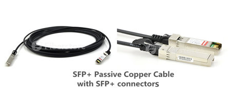
SFP+ copper twinax direct-attach cables from Cisco are developed as a cost-effective alternative for very short links in high-speed interconnect application within racks and across adjacent racks. This SFP+ passive copper cable assembly uses twinax shielded cable with robust die cast connector interfaces for enhanced support of high frequency data rates, which means signals travel over parallel pairs of conductors. 10G SFP+ twinax copper cables contains 2 pairs—one for transmit (Tx) and one for receive (Rx) and each shielded pair is surrounded by an overall shield. Cisco passive twinax cables are offered in different lengths of 1, 1.5, 2, 2.5, 3 and 5 meters. I know you are quite familiar with SFP+ passive copper cable, now let’s get down to the role of the 10G SFP+ passive DAC cables.
What Is the Role of the 10G SFP+ Passive Copper Cable?
10G SFP+ passive copper cable is effectively viewed as a transparent cable to the switch and requires little to no direct power to operate. It seems that a passive cable just acts as a pass-through transmission medium and do nothing to the signal, then how exactly is the signal processed in the first place? In most cases, this activity resides exclusively inside the electronic circuitry of the switch. The switch will generally perform the following functions to the signal prior to its transmission through the cable assembly:
- Signal Conversion
Signal conversion occurs first in instances where electrical circuits must interface with optical circuits. Since some switches operate select ports in the optical domain (i.e. fiber optic light pulses), that optical signal must then be converted over to an electrical signal that can be further modified and reliably sent over an electrical transmission medium such as copper cabling.
- Signal Conditioning
Signal conditioning is in essence preparing the signal for the next step of the process. This could involve formatting the signal using a standardized electrical modulation pattern that other down-stream equipment can recognize. This could be conditioning the signal into a 10-bit/8-bit pattern where 8-bit segments of data require encapsulation in a 10-bit "packet†featuring additional header information that is used for error correction and re-transmission mechanisms.
- Signal Amplification
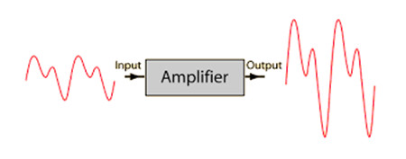
The next critical step, signal amplification, will raise the newly conditioned signal from a low-strength "machine level†signal to a far more powerful or amplified signal. Signals are kept at lower strength levels inside the switch’s processing architecture for several reasons, including reduced power consumption, improved heat dissipation, reduced noise/interference characteristics and so on. However, this internal "baseband†signal is far too weak to travel the typical distances commanded by cable assemblies. Theyâ€re only designed to travel a few inches around a PC-board or chipset!
- Signal Equalization
Now, if we were dealing purely with signals of past eras such as 10/100 Megabit (Fast) Ethernet, the final phase known as signal equalization would be totally unnecessary. However, a signal such as the one sent over SFP+ Cables requires hundreds of MegaHertz (MHz) or even GigaHertz (GHz) of signal bandwidth to operate effectively. The problem with such wide-banded signals is that the lower portion of the signal may arrive at the other end of the cable faster or stronger than the higher portion of the signal. This causes an anomaly known as time delay and/or phase delay SKEW that absolutely wreaks havoc on the signal itself, sometimes to the point of being unrecoverable.
To avoid this, the signal must be equalized accordingly. On the transmission channel of the link, the signal must go through a process called Pre-Emphasis. It does exactly what it sounds like—it pre-emphasizes (boosts) the portion of the signal that tends to get skewed. Similarly, on the receive channel of the link, the signal portion must be reciprocally de-emphasized (lowered). This complete process of equalization equalizes the signal so that it is uniform and free of SKEW and therefore ready to be sent over a specific transmission medium, i.e. a SFP+ passive DAC cable.
Third-party Cisco SFP+ Passive DAC Twinax Cable
Enterprises today are seeking to cut down the costs, but the original Cisco SFP+ passive copper cable are very expensive. Therefore 3rd-party SFP+ optics with its lower price is the ideal choice.
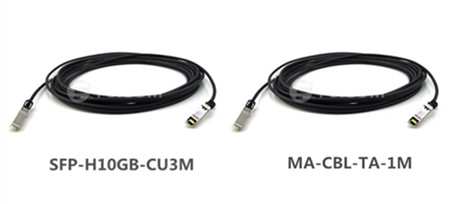
- SFP-H10GB-CU3MSFP-H10GB-CU3M from Fiberstore is a Cisco compatible 10GBase-CU SFP+ to SFP+ direct attach cable that operates over passive copper with a maximum reach of 3.0m. It has been programmed, uniquely serialized, and data-traffic and application tested to ensure it is 100% compliant and functional. Our direct attach cables are built to comply with MSA (Multi-Source Agreement) standards. Our 10G SFP+ passive copper cables are well-tested before shipping worldwide and cost much lower than the original ones.
- MA-CBL-TA-1MMA-CBL-TA-1M from Fiberstore is a Cisco compatible SFP+ to SFP+ direct attach cable that operates over passive copper with a maximum reach of 1.0m. This is a twinax cable featuring two male SFP+ connectors.
Conclusion
Cisco 10G SFP+ passive copper direct attach cable is defined for 10GbE applications over passive copper cable within a very short reach, but its popularity are largely limited by the high cost. Thus people are seeking to purchase from OEM vendors like Fiberstore. All products offered by Fiberstore are tested in-house to ensure that they will arrive in perfect physical and working condition.
Posted by: angelina at
04:09 AM
| No Comments
| Add Comment
Post contains 1015 words, total size 8 kb.
April 20, 2016
SFP is a new generation of optical module transceivers. Featured by the compactness, flexible and economical design and high performance, SFP transceivers soon replace all the existing interface standards in networking after certification. To satisfy some projects, whose telecommunication equipment or networking device needs optical transceiver requirement. For better sharing SFP transceiver modules, this blog is illustrating knowledge of this hot-pluggable transceiver.
Small Form Factor Pluggable (SFP) Definition
The SFP transceiver is specified by Multisource Agreement (MSA), which was developed and followed by different transceiver manufacturers. SFP transceivers have a wide range of detachable interfaces to multimode or single-mode fiber optics, which allows users to select the appropriate transceiver according to the required optical range for the network.
Main Features of SFP Transceiver
SFP transceiver stands for Small Form-factor Pluggable transceiver. This transceiver is compact and hot-pluggable. It is widely used in the field of Data Communication and Networking. This transceiver mainly acts as an interface between a networking switch and its interconnecting cable as shown in Figure 1. This networking device can be any switch, repeater, router, multiplexer etc. The interconnecting cable may be made of copper or it can be an optical fiber cable. This transceiver which interfaces a device in the network to the cable is highly popular and can support devices and cables of various network vendors.
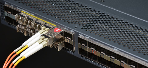
Superseding the GBIC transceiver, SFP modules are also called "mini-GBIC†due to their smaller size. By choosing the appropriate SFP module, the same electrical port on the switch can connect to fibers of different types and different wavelengths. If the fiber is upgraded, the SFP module is replaced.
Optical SFP transceivers come with digital monitoring features with the help of which one can monitor the performance of SFP in real time. This feature can be used to monitor SFP’s performance parameters like working temperature and wavelength, supply voltage, optical input and output etc. These transceivers have a PCB in them which connects to an electrical connector designed for SFP. SFP transceiver also has a 256 byte EEPROM memory. SFP transceivers are housed in a metal enclosure and their power dissipation is low. They operate over a wide temperature range and support a large number of different types of cable. An improved version of SFP standard called SFP+ can support transmission rates up to 10Gbps.
Certain SFP transceivers can also use copper cables as interface. This will cause a device in the network to send their data over shielded or unshielded twisted pair cable. Usually such copper cable interfaces are used when the information to be transmitted needs to cover only shorter distances where use of copper cable is more economical than optic fiber cables.
Types
SFP transceivers are of various types and each type comes with different configurations of transmitter and receiver. It is important to choose a proper transceiver to act as an interface between the device and the cable. This choice of transceiver is usually made based on the type of fiber optic cable. Such SFP transceivers which are used to provide the necessary reach to a fiber optic cable are categorized as optical SFP. These SFP modules are of several versions, wherein each version has different values of working wavelength and working distance: typical wavelength of different modules are 850 nm, 1310 nm and 1550 nm with working distances of 550m (SX), 10 km (LX) and 40 km (XD) respectively. J4858B and E1MG-LX-OM are 1000BASE-SX and 1000BASE-LX SFP, which are greatly welcomed by users. And there are also other types of SFP like DWDM, CWDM and bi-directional SFP with single fiber having upstream and downstream working wavelengths of 1310 nm and 1490 nm.
SFP vs. GIBC
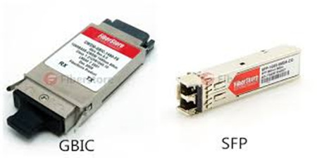
SFP transceivers are compatible with a number of communication standards like Ethernet, SONET along with many other standards. SFP is an upgraded version of Gigabit Interface Converter (GBIC) module. SFP uses LC fiber optic cable for its interface whereas SC cable interfaces are used in GBIC. SFP is more space saving than GBIC, since the former has only half the size of the latter. SFP has transmission rate ranging from 100Mbps to 4Gbps and it can work at distances ranging between 500 meters to hundreds of kilometers. The ‘hot-pluggable’ feature of SFP makes it flexible. Any future changes can be easily incorporated into the SFP module, while the maintenance of the module is also made easier by this hot-pluggable nature of SFP, thereby making it compact.
XFP and SFP+ for 10 Gigabits
Larger than SFP, XFP transceivers were the first to handle 10 Gigabit Ethernet optical lines, because SFP supported only up to 4.25 Gbps. The same module size as SFP, SFP+ was later introduced to handle 10 Gbps but required more circuitry in the host device. As a result, SFP+ ports are mostly found in plug-in cards for servers and enterprise switches. See transceiver and GBIC. SFP+ and XFP Modules SFP Gigabit Ethernet and SFP+ 10 Gigabit Ethernet transceivers are the same size.
Summary
To sum up, SFP transceiver modules are designed for use with small form factor connectors, and offer high speed and physical compactness. Thus many telecom vendors have manufactured a variety of SFP transceivers to meet their common objectives of broad bandwidth, small physical size and mass, and ease of removal and replacement.
Posted by: angelina at
02:12 AM
| No Comments
| Add Comment
Post contains 881 words, total size 7 kb.
April 14, 2016
According to different fiber types, fiber optic connectors can be classified into standard fiber optic connectors, small-form factor (SFF) fiber optic connectors and ribbon fiber connectors. With the increasing deployment of fiber in the LAN, especially for building and campus backbone installation, the the use of SFF fiber optic connectors is becoming more widespread. Of which LC connector has been considered to be the ideal solution for Enterprise applications. This post will briefly introduce LC connector and its application in fiber management and optical transceiver.
What Is LC Connector?
The LC connector is sometimes called "little connectorâ€. It is approximately half the size of an SC connector. The LC has a back shell designed to accommodate standard 1.6mm or 2.0mm diameter cable designs. The standard construction of the LC connector consists of a spring loaded, 1.25mm diameter zirconia ceramic ferrule housed in a thermoplastic connector back shell.
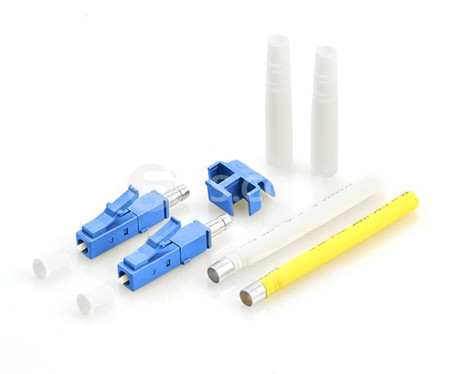
In the emerging SFF connector landscape, the LC connector is becoming the preferred transceiver connector for high bit rate applications (1Gb/s and above) due to its numerous advantages for transceiver design. More transceiver manufacturers support the LC interface than any other SFF connector, and LC transceivers are available from numerous sources for applications ranging from 10 Mb/s to 10 Gb/s.
Why Choose LC Connector?
The LC connector, developed by OFS Laboratories, represents the next-generation SFF connector. But why should we choose LC connector? The LC connector solution reduces the space required on panels, outlets and in closets by approximately 50% throughout the network. It simplifies moves, adds and changes and helps save you money. The LC connector uses an improved version of the familiar, user-friendly RJ-style telephone plug that provides a reassuring, audible click when engaged.
The new, one-piece design enhances the connector’s durability and meets side-load requirements of standard 2.5mm connectors. The connector can only be installed into the adapter in one orientation thus maintaining proper polarization and alignment. The straight-in motion significantly reduces debris and enhances optical performance. The unique combination of small size and the click of connectivity make LC connector the right choice for today’s high performance networks.
The LC Connector in Fiber Management and Transceivers
The LC connector system was designed specifically to address the needs of increasing network interconnect density. In the past, fiber management systems have required twice as many individual connectors as copper systems, hence, crowding racks and closets with additional patch bays, management hardware and line terminating electronics. The LC connector provides the potential for twice the interconnect density in closets and racks when compared to a SC connector. Although, there is a point at which additional density cannot be utilized because of the difficulty in fiber routing inordinately large cable counts. Also at issue in these higher density racks, is the problem of disturbing adjacent circuits in MACs. Most important in fiber management, is the decreased footprint of the LC on electronics (hubs, switches, etc.) for fiber transceivers.
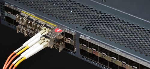
Original SFF transceivers (GBICs) on equipment have now been overshadowed by the SFP transceiver. Equipment vendors are starting to offer SFP on switches/NICs for 1Gb/s Ethernet. The optical receptacle on the SFP for Fibre Channel and Gb/s Ethernet is the LC connector. Most major transceiver vendors now sell SFPs with the LC interface.Figure 2 shows a 1000BASE-SX SFP (eg. TL-SM311LM) with LC duplex connector. For example, On 200 pin XenPAK transceivers, only SFF options are specified in the Multi Source Agreement (MSA). The LC is also used in competing transceivers such as XenPAK, X2 and XFP. 10Gb/s Standards are driving network planners to upgrade infrastructure hardware (fiber, cable management and interconnect) and to prepare their network Storage Area Networks and Fiber Backbones to be able to utilize these high-speed transceivers. For example, SFP-10GB-SR is 10GBASE-SR SFP+ that can transmit 10Gb/s on the LC connector.
Conclusion
Based on a wide range of criteria that cover issues relevant to infrastructure requirement, the LC connector offers clear advantages over its performance. With LC connector system, users effectively double interconnect density without the added expense of additional fiber management systems.
Posted by: angelina at
02:07 AM
| No Comments
| Add Comment
Post contains 679 words, total size 6 kb.
April 12, 2016
Small form factor pluggable (SFP) optical transceiver nowadays is commonly utilized in the telecom field for Ultra-high-speed transmission applications as well as for low-cost applications. Characterized by small form-factor, pluggable and self-diagnose, Gigabit SFP transceiver becomes the most popular application for fiber optic systems including asynchronous transfer mode (ATM), FDDI, fiber channel, fast Ethernet and gigabit Ethernet, and synchronous optical network (SONET)/synchronous digital hierarchy (SDH). SFP transceiver has dominated the market over a long time. Recently many vendors provide SFP transceiver with different specifications, but SFPs from Cisco are the standardized optical transceivers which are greatly favored by users. People may know what SFP transceiver is, but do they really know about SFP transceiver? The following article will offer a brief introduction to Cisco SFP first, then go further to the basics of the SFP transceiver.
Cisco SFP Module
Cisco industry-standard SFP modules can link your switches and routers to the network as shown in Figure 1. This hot-swappable device plugs into a Gigabit Ethernet port or slot. SFP transceiver are available in optical or copper models that can be used on a wide variety of Cisco products and intermixed in combinations of 1000BASE-T, 1000BASE-SX, 1000BASE-LX/LH, 1000BASE-EX, 1000BASE-ZX, or 1000BASE-BX10-D/U on a port-by-port basis.
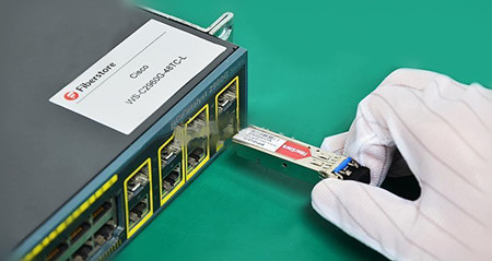
Take 1000BASE-LX/LH SFP as an example, it is compatible with the IEEE 802.3z 1000BASE-LX standard for both multimode and single-mode fibers. The 1000BASE-LX/LH SFP like GLC-LX-SM-RGD, operates on standard single-mode fiber-optic link spans of up to 10 km and up to 550 m on any multimode fibers. When used over legacy multimode fiber type, the transmitter should be coupled through a mode conditioning patch cable. Some people may feel confused about the term—1000BASE-LX/LH. In fact, it is created by telecommunication vendor, but not a ratified standard. Cisco GLC-LH-SM is also a type of this SFP transceiver that is compatible with 1000BASE-LX standard. The only difference between GLC-LX-SM-RGD and GLC-LH-SM lies in the function of Digital Optical Monitoring support. Since we are familiar with the Cisco SFP transceiver, let’s move onto the structure of SFP.
The Structure of SFP
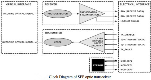
SFP transceiver is called Mini-GBIC for its smaller form-factor structure. A low-cost fiber optical transceiver circuit typically includes transmitter and receiver. The transmitter is composed of LD, Reference generator, laser bias circuit, PECL Input buffer, Laser modulation-circuit, Laser bias circuit, Automatic power control, and Failure detection. The receiver is made up of PD, Input biasing, Auto-zero circuit, power supply decoupling &optimizing sensitivity, lever detector and so on. A photodiode preamplifier, an active band-pass filter, and an instrumental amplifier is experimentally achieved. Using the proposed circuit for measurement and on-line automatic monitoring, the efficiency of fiber-optic characteristics monitoring can be enhanced and on-line noise interference can be suppressed. The transfer functions and frequency response of the optical receiver are derived.
Optic Transmitter and Receiver
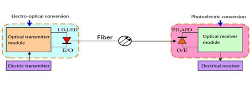
The key component of an optical receiver is its photo detector. The major function of a photo detector is to convert an optical information signal back into an electrical signal (Photocurrent). The photo detector in today's fiber - optic communications systems is a semiconductor photodiode (PD). This miniature device is usually fabricated together with its electrical circuitry to from an integrated package that provides power-supply connections and signal amplification.
The Working Principle of SFP Transceiver
From the above diagram, we can see that a SFP transceiver contains both transmitter and receiver in a single module. But how does a SFP transceiver work? In fiber optic data links, the transmitter takes an electrical input and converts it to an optical signal, which is coupled with a connector and transmitted through a fiber optic cable. The light from the end of the cable is coupled to a receiver, where a detector converts the light back into an electrical signal. In short, as the core of the optical communication devices, optical transceiver module completes optical signal light-electricity/electricity-light conversion function.
Conclusion
After going through this passage, you may have a clearer mind about the SFP transceivers. High performance and low cost SFP optic transceiver is highly desirable for fiber optic communications, but we can’t ignore the fact that SFP can only support up to 4.25 Gbps. For higher data rate like 10GbE or 40GbE, there are other optical transceivers to support them.
Posted by: angelina at
02:27 AM
| No Comments
| Add Comment
Post contains 862 words, total size 7 kb.
April 07, 2016
Since most data centers today are fueled by more data and great bandwidth, all optical technology including optical transceivers, must face the increasing demand for bandwidth. The technology needs to meet the bandwidth requirements not only for storage and switch applications but also for server applications. From the old 100 mbqs to the existing 40/100G Ethernet, optical transceivers has improved itself to keep path with the higher data rate. Here is what you need to know about optical transceivers and server technology.
Optical Transceivers: Smaller, More Affordable and Less Power Hungry
Network designers require transceiver modules that consumes less power and costs less while being smaller in size. For instance, the packages for optical transceivers are shrinking. They evolved from a 4" x 3.5" footprint to a 2.3" x 0.68" package. This is an essential evolution for optical transceivers as it allows the overall footprint of servers to decrease, making data centers smaller and more streamlined.
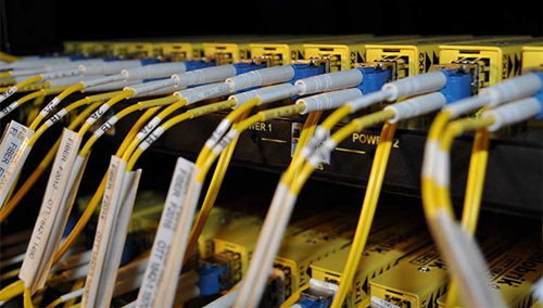
In addition, optical-transceiver power consumption has dropped from 10 W to 3 W or lower—a significant stride that has enabled designers to get more out of transceiver technology. Lower power consumption means lower prices in the design and in power costs. These savings are incredible for people in the technology field.
Port density is another important factors in transceiver design. Most data centers consist of multiple racks of switching equipment that can achieve high speeds. To control costs, designers have refined their designs and tried to improve their manufacturing process technologies to assist with this effort. Increasing port density is just one way to decrease system costs.
The Evolution Path of the Optical Transceiver
As noted before, optical transceivers that met the above requirements are typically recognized in the technology world through the SFP multi-source agreement (MSA). Nowadays, the data center have consolidated around optical transceivers in the SFP form factor for server access and around QSFP transceivers for switch-to-switch interconnects. Moreover, when the distance to the access port is less than 5 meters, direct attach copper cables are usually utilized while active optical cables are used for longer distances.
SFP+ (Enhanced Small Form-factor Pluggable ) transceiver plays a key role in 10G transmission with its advantage of compactness, performance and cost savings. For example, JD092B just like other SFP+ modules are widely used in 10G access ports for a long time. However, the situation will be changed in the near future when the access speed increases to 40G and the 10G access ports turn to QSFP. QSFP transceiver is a parallel transceiver which accept 4 electrical input lanes, and operate at 4 x 10 Gbps. Today, 40G QSFP+ like JG661A is widely deployed in data center switching fabrics and ramping up hard as data centers deploy 40GbE, particularly as a high-density 10G interface via breakout cables.
However, IHS Infonetics released a research in May this year which said QSFP28 modules will be deployed in high volumes as data centers transition from 40G to 100G switching fabrics starting in 2016. What’s QSFP28? As we know, the first-generation QSFP transceivers are equipped with four Tx and Rx and each channel has a rate of 10 Gbps. But now each channel of QSFP can transmit and receive data up to 28 Gbps thanks to the development of technology. This type of transceiver is called QSFP28 which is a new trend for 100G applications.
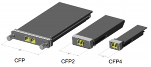
The widely recognized path to achieve 100G is "10GbE-40GbE-100GbEâ€. And the first fiber optic transceivers that were shipped with 100G transceivers were CFP. But CFP2 soon came along and achieved 5 x 25G (or 10 x 10G) lane electrical interface while it reduced the form factor by half of CFP. Even so, it costs too expensive and the its footprint is too large to trigger mass deployment. After CFP2, CFP4 which is half the size of the CFP2 has been launched. Meanwhile, there is another form factor namely QSFP28 mentioned above competing with it.
Optical Transceivers and Server Technology Affect Each Other’s Performance
Increased bandwidth is the everlasting topic of telecom field. And just as the saying goes, a man without distant care must have near sorrow. To cope with the ever-increasing bandwidth, every designer must find solutions that will optimize the systems they are designing or implementing for future proofing.
Despite how revolutionary optical transceivers were back when it was first created, it was a rudimentary tool at best. The demand for high port density transceivers started back in 2003 and since then, these devices have become increasingly smaller in a short amount of time. Optical transceivers with smaller packages actually play an important role in reducing overall server footprint, and smaller transceivers means smaller and more streamlined data centers.
Apart from making data centers smaller, the reduction of transceiver sizes also means that it uses less power, which in turn means lower prices as far as power costs and designing is concerned. This is a significant development in transceiver technology, and is shaping the way designers create these devices and get more out of it as an innovative technology.
Data centers are processing tons of data and need to retrieve at record speeds, which requires that every aspect of the design be optimized, including the optical transceiver technology. The above article has concluded several points about how optical transceiver react to the server technology.
Posted by: angelina at
06:11 AM
| No Comments
| Add Comment
Post contains 891 words, total size 7 kb.
April 01, 2016
Nowadays one and 10 Gbqs data rates are not adequate to meet the continued requirement for expansion and scalability in the data center, thus technology evolves and standards are completed to define higher data rates such as 40/100G Ethernet. In the meanwhile the cabling infrastructures installed today must provide scalability to accommodate the need for more bandwidth in support of future applications. OM3 and OM4 multimode cabling solutions have been proven to be a cost-effective solution for 40G data center. Today’s article will make you familiarize with this new Gigabit Ethernet and OM3/OM4 cabling to help you smoothly upgrade to 40G Ethernet.
Multimode Fibers in Data Center
Multimode fiber is more popular in data centers than singlemode fiber. Many people may know the reason—budget. Because the price of multimode fiber is typically much lower than singlemode fiber. Additionally, multimode fibers utilizes the low cost 850nm optical transceiver for both serial and parallel transmission. While singlemode fiber uses the expensive 1310nm and 1550nm transceiver and duplex fiber wavelength division multiplexing (WDM) serial transmission. Therefore, most data center designers would choose multimode fiber for 40/100G transmission.
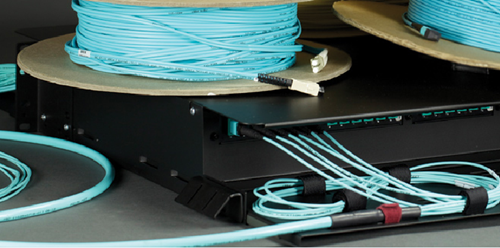
There are four common types of multimode fibers available in the market—OM1, OM2, OM3 and OM4. Recently OM3 and OM4 cables are gradually taking place of OM1 and OM2 multimode cable. OM3 and OM4 are laser-optimized multimode fibers with 50/125 core, which are designed to accommodate faster networks such as 10, 40 and 100 Gbps. Compared with OM1 (62.5/125 core) and OM2 (50/125 core), OM3 and OM4 can support high data rate and longer distance. This is why OM3 and OM4 is more popular in data center.
The Ratification of IEEE 802.3ba
The Institute of Electrical and Electronics Engineers (IEEE) 802.3ba 40G/100G Ethernet standard was ratified in June 2010. According to this standard, it includes detailed guidance for 40/100G transmission with multimode and singlemode fibers. But the standard does not have guidance for Category-based unshielded twisted-pair or shielded twisted-pair copper cable.
OM3 and OM4 are the only multimode fibers included in 40/100G standard. Because multimode fiber uses parallel-optics transmission instead of serial transmission due to the 850-nm vertical-cavity surface-emitting laser (VCSEL) modulation limits at the time the guidance was developed. Compared to traditional serial transmission, parallel-optics transmission uses a parallel optical interface where data is simultaneously transmitted and received over multiple fibers. Table 2 shows the IEEE standards for 40 and 100 GbE.
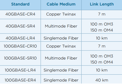
The 40G and 100G Ethernet interfaces are 4x10G channels on four fibers per direction, and 10x10G channels on 10 fibers per direction, respectively. For 40GBASE-SR4 transceivers, it utilizes multimode fiber for a link length of 100m over OM3 and 150m over OM4. QSFP-40G-SR4 is Cisco 40GBASE-SR4 QSFP+ that can both operate over OM3 and OM4 cables to achieve 40G connectivity just as FTL410QE2C.
OM3 or OM4?
As noted before, OM3 and OM4 can meet the requirement for 40G migration cabling performance, that’s why they are being widely utilized in 40/100G migration. But OM3 and OM4, which is better for your infrastructure? There is no exact answer to this question as numerous factors can affect the choice. The working environment and the total costs are always the main factors to be considered when selecting OM3 or OM4 multimode cable.
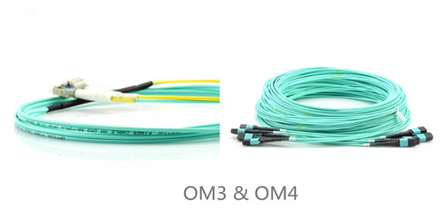
OM3 is fully compatible with OM4. They use the same optical connector and termination of connector. The main difference between them is in the construction of fiber cable that makes OM4 cable has better attenuation and can operate higher bandwidth at a longer distance than OM3. On the other hand, the cost for OM4 fiber is higher than OM3. As 90 percent of all data centers have their runs under 100 meters, choosing OM3 comes down to a costing issue. However, in the long term, as the demand increases, the cost will come down. OM4 will become the most viable product in the near future.
Conclusion
No matter choosing OM3 or OM4 for your infrastructure, 40G migration is in the corner. OM3 and OM4 multimode cable featured by the high performance and low cost are the perfect solution for 40/100G migration.
Posted by: angelina at
02:42 AM
| No Comments
| Add Comment
Post contains 684 words, total size 6 kb.
32 queries taking 0.065 seconds, 91 records returned.
Powered by Minx 1.1.6c-pink.

